Hi there, and welcome to this monthly UHK status update!
We keep catching up with pending orders as quickly as possible, and we plan to take it up a notch by adding a new busy elf to our assembly team of athletic Hungarian elves.
We’re working on some major Agent and firmware features that will allow configuring the speed and behavior of modules and so much more. There’s no ETA yet, and we’ll share more details when the time comes.
New orders are expected to ship in May, and we’ll update the delivery status page every weekend.
We still only have black cases. If you have a pending order containing a UHK 60 v2 with a non-black case or an extra non-black case, we won’t send your pending orders to production until we have non-black cases in stock unless you ask us to switch the case colors of your order to black by filling out this form.
As soon as we get non-black cases, we’ll publish an exclusive newsletter with a form with which you’ll be able to switch (back) to your desired case color.
Meanwhile, on Twitter, the companionship of ultimate hackers never ceases to amaze us:
Thanks for reading this update! We’ll be keeping you updated on all things UHK and plan to publish the next update at the end of February.
Hi there, and welcome to this monthly UHK status update!
We're happy to say that despite the holidays, the UHK 60 v2 production volume of December was even higher than November, which already hit a record. We keep catching up with pending orders as quickly as we can, and we’ve been assembling UHKs between the holidays.
New orders are expected to ship in April, and we’ll update the delivery status page every weekend.
We expect production to peak in January, given the lack of holidays and some manufacturing optimizations we’ve implemented.
We still only have black cases. If you have a pending order containing a UHK 60 v2 with a non-black case or an extra non-black case, we won’t send your pending orders to production until we have non-black cases in stock unless you ask us to switch the case colors of your order to black by filling out this form.
We expect to get colored cases in January. As soon as we get them, we’ll publish an exclusive newsletter with a form with which you’ll be able to switch (back) to your desired case color.
We’re delighted to hear from UHK 60 v2 customers as they receive their orders!
Finally have the UHK 60 V2 in place and hot damn this thing was worth every penny and every day. No compromises in the @UltHackKeyboard design, manufacturing, or software. Single best board I’ve been had my hands on. Feels like home. #uhkv2#ultimatehackingkeyboardpic.twitter.com/cpxdxNaS0X
The agent software package cannot be overstated as a triumph of UX and integrated design. This whole product offering is a triumph of #opensource design and general customer-obsessed product development. I can't remember the last time new hardware was this sensibly done and easy.
Thank you @UltHackKeyboard! The board is comfortable and my shoulders will thank me. No need for a mouse now. Both Product and packaging are of high quality.Worth the wait. pic.twitter.com/q8duTHcBRM
Hi there, and welcome to this monthly UHK status update!
TL;DR: UHK 60 v2 production volume was in the hundreds in November, allowing us to combat the backlog of pending orders effectively. We’re catching up, and production progress will keep accelerating. New orders are expected to ship in April, and we’ll update the delivery status page every weekend.
We’re happy to say that production is slowly but surely getting smoother, and this month, we were finally able to produce not a meager 50 or 60 but hundreds of UHKs. We’re well on our way to catching up.
We’ll keep accelerating manufacturing progress. Due to holidays, the progress of December is expected to be similar to November, and we expect to achieve peak progress in January.
We still only have black cases. If you have a pending order containing a UHK 60 v2 with a non-black case or an extra non-black case, we won’t send your pending orders to production until we have non-black cases in stock unless you ask us to switch the case colors of your order to black by filling out this form.
We expect to get non-black cases in January or possibly in late December. As soon as we get them, we’ll publish an exclusive newsletter with a form with which you’ll be able to switch (back) to your desired case color.
We’re delighted to hear from UHK 60 v2 customers as they receive their orders!
Hi there, and welcome to this monthly UHK status update!
TL;DR: We’ve delivered about sixty UHK 60 v2 orders in October. We plan to ship hundreds of orders per month starting from November. The v2 palm rests and extra feet are finally ready to ship. We’ve added several spare parts to our webshop. A new Agent version has been released, supporting arbitrary scancodes and restoring preloaded keymaps.
Production progress
In October, we received the much-anticipated mechanical support parts we told you about in our previous update. We’ve tested the parts, and they work just as expected, and socket separation shouldn’t be an issue going forward.
Unfortunately, we had to wait for the parts for quite some time, which halted production, resulting in only sixty assembled UHK 60 v2 units in October instead of the originally planned hundred units. We shipped many of these units at the end of October, so these days were quite a rush.
Luckily, we have also received the missing v2 palm rest parts and extra feet, so customers who ordered such items will be queued on a first-come, first-served basis.
We still only have black cases, so orders containing UHK 60 v2 items with non-black cases or extra non-black case items won’t be sent to production until we have non-black cases in stock unless you ask us to switch the case colors of your order to black by filling out this form.
We plan to manufacture hundreds of UHK 60 v2 units starting in November, enabling us to combat the backlog of pending orders effectively. We’re eager to receive many tweets like Peter’s.
New orders are expected to ship in March, and we’ll update the delivery status page every weekend.
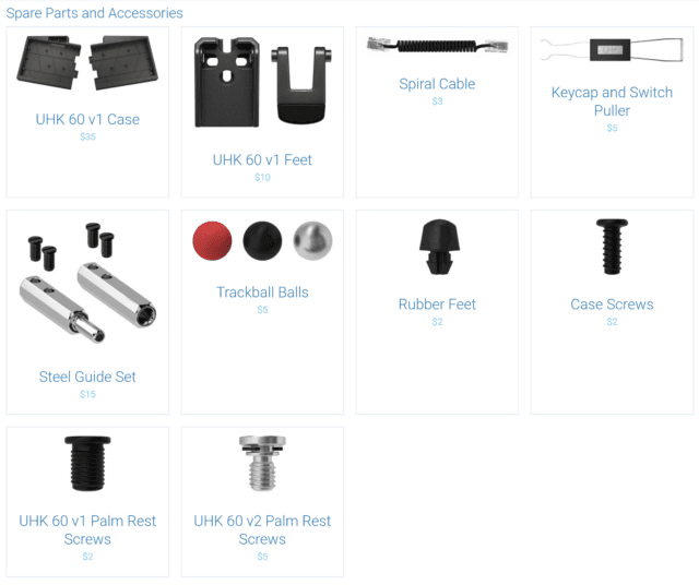
Spare parts bonanza
A long time ago, during our crowdfunding campaign, I wrote an article on repair and how we planned to enable our customers to fix their UHKs if needed. Fast-forward six years, we’ve written many repair guides; we provide repair assistance and in-warranty repair service for free and out-of-warranty repair service for very reasonable prices.
Many people may not know, but we also provide spare parts. Until this point, a very limited selection of spare parts has been available in our webshop, and the rest of the spare parts were only available via our customer support. To further our dedication to the noble cause of repair, we’ve added several additional spare parts to our webshop, so should you need any spare parts, you can pick them up and check out in no time.
Your UHK is an investment that should serve you for years to come. Don’t throw it away if it has been broken. Feel free to reach out to us, and we’ll help you make it shine in its former glory. As for the selection of the spare parts of our webshop, it’s only expected to grow.
New Agent features
There are two major features of the new Agent 1.5.16 release that are worth mentioning.
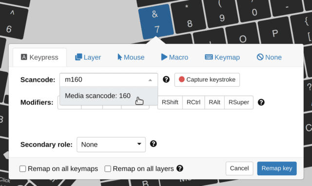
Custom scancodes
The first feature is arbitrary scancodes. The scancode dropdown of Agent provides quite a few scancodes that should satisfy most needs, but some want more scancodes, for example, to bind special shortcuts that surely don’t interfere with other shortcuts. This group of users may find the arbitrary scancodes feature very handy. To explain this feature, we have to get a bit technical.
There are three scancode types according to the USB interfaces that the UHK exposes:
The basic keyboard interface implements the Keyboard/Keypad Page, which contains alphanumeric, navigation, and regular scancodes. See chapter 10, page 53 of HID Usage Tables. Scancode type abbreviation is B for basic.
The media keyboard interface implements the Consumer Page, which contains volume adjusting and other media scancodes. See chapter 15, page 75 of HID Usage Tables. Scancode type abbreviation is M for media.
The system keyboard interface implements the Generic Desktop Page, which contains sleep and power-down scancodes. See chapter 4, page 26 of HID Usage Tables. Scancode type abbreviation is S for system.
As for the valid numeric intervals of the scancodes, it's 1-255 for basic and system scancodes and 1-65535 for media scancodes.
You can write a string composed of the scancode type and scancode number into the scancode field to specify the desired scancode. Examples are B40, M160, and S10.
Agent substitutes the specified scancode with its well-known name if the scancode dropdown contains it. For example, the B40 scancode gets substituted with Enter. Otherwise, Agent will display the scancode as it is.
The range of available scancodes is huge, hosts recognize only some, and different operating systems and applications recognize different sets of scancodes.
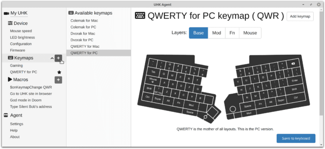
Pre-loaded keymaps
The second new Agent feature allows you to add pre-loaded keymaps.
The UHK is preloaded with six keymaps: QWERTY for PC and Mac, Dvorak for PC and Mac, and Colemak for PC and Mac. You probably don’t use all of these keymaps, so you can delete the unused ones in Agent to minimize clutter. Up until this point, you couldn’t restore the deleted preloaded keymaps, but now, you can by using the plus icon next to the Keymaps menu item of the side menu.
Thanks for reading this update! We’ll be keeping you updated on all things UHK and plan to publish the next update at the end of November.
Hi there, and welcome to this slightly delayed monthly UHK status update!
TL;DR: We’ve delivered about 50 UHK 60 v2 orders in September, and the overall feedback was great, but a customer reported a production issue that can affect other customers as well. We ensure that this issue won’t reoccur going forward, delaying production by a week or two. We plan to ship about 100 UHK 60 v2 orders in October and keep ramping up production.
TL;DR 2: Due to various factors, order fulfillment is not yet strictly executed on a first-come, first-served basis. If your UHK 60 v2 has a non-black case, your order can get further delayed. We can change your UHK 60 v2 case color to black if you fill out this form. New orders are expected to ship in February 2022. Read on for more details.
We’re delighted to hear from UHK 60 v2 customers as they received their orders!
@UltHackKeyboard the UHK v2 just arrived and it is fantastic. I like the feet, they need quite a bit of force to lock them in place. I opted for the tenting setup. With my uhk v1 I have four screws to tent the thing. This is much better. Thank You! Great Job.
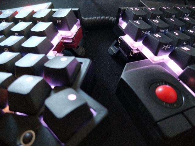
@UltHackKeyboard the lights change when You press mouse or mod key. Very cute, although I don't look at the keyboard when I type. USB C is definitely an improvement. The key grab thingy works well. The cable between the halves is now textile wrapped, which looks better. pic.twitter.com/ZtzSpoQCgt
@UltHackKeyboard just received my UHK v2! I have to say I am very impressed! Compared to v1 the build quality is so much better! Love the braided cables as well and especially the keycaps with the nice grippy feel. Lubing my switches this weekend now then it’s perfect 👍 pic.twitter.com/QKTRdjM5l8
Sadly, Ben reported after his initial tweet that three sockets of his UHK separated from the PCB when he replaced all the switches. Socketed keyboards are affected by this issue, but three sockets are too much to be considered normal.
Going forward, our contract manufacturer will use more solder for the sockets, and we’ll add mechanical support to prevent such issues. The mechanism for mechanical support will be the same we’ve been using for the key cluster module. For the record, we’ve delivered thousands of key cluster modules and haven’t received any complaints about separated sockets.
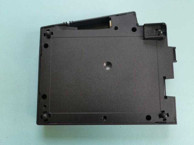
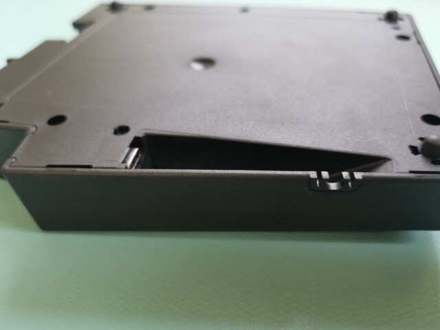
For the time being, we’ll use extra parts within the case for adding mechanical support. Later, we’ll integrate this solution to the bottom case parts by modifying their molds. We’re chasing the latter solution because it makes manufacturing easier and faster. Consequently, we won’t manufacture non-black cases until the mold gets modified, which should take about three months.
We currently only have black cases in stock, so if you’re early in the queue and don’t want your order to get further delayed than necessary, switch to a black case by filling out this form. You can check your order parameters several days after you submit the form.
When will my order arrive?
New orders are expected to ship in February 2022.
As for earlier orders, the following factors inhibited us from shipping on a first-come, first-served basis:
I realized about a week ago that our order allocation algorithm was still buggy and didn’t respect our first-come, first-served principle. I fixed the bug, tested it, and it won’t be an issue in the future.
We don’t have palm rests and extra v2 feet in stock, so orders containing these items aren’t sent to production. We expect to have stock in two weeks, at which point this will be a non-issue.
Only UHKs with black cases will be shipped until modifying the mold to add the mentioned mechanical support mechanism. We expect to manufacture non-black cases about three months from now. Again, you can switch to a black case according to the above instructions.
Consequently, if your order hasn't shipped yet and you see an order number larger than yours shipped, it doesn’t mean that there's something wrong with your order. If your order is in the “processing” state, we'll ship it as soon as possible. Please check the status of your order before emailing us.
Hi there, and welcome to this monthly UHK status update!
TL;DR: UHK 60 v2 production has finally started, earliest orders will ship in September, and new orders are expected to ship in January 2022. Every Crowd Supply order has been shipped, and almost all module orders of UHK 60 v1 customers have been shipped.
Please note that these are unusually busy days, and as a result, our support response time is considerably longer than usual. It may take some days to get back to you, but we will get back to you.
UHK 60 v2 production progress
After multiple delays, I’m delighted to say that all the needed parts have arrived and UHK 60 v2 production has finally started. The earliest orders will ship in September. We’ll work hard to fulfill pending UHK 60 v2 orders and catch up. If you purchase now, we expect to deliver your order in January 2022.
Don’t expect our UHK 60 v2 production volume to be high in September, as we still have some modules to ship, and launching the production of a new product is usually a bit slow in the beginning.
Module production progress
We’ve shipped every Crowd Supply order. If you haven’t received yours yet, chances are it’s already in transit.
We plan to ship pending module orders in the next two weeks to every customer who hasn’t ordered a UHK 60 v2.
As for the rest of the module orders, we’ll ship them together with UHK 60 v2 units.
Your tweets
You guys keep sending your tweets, and we're always eager to read and feature them! If you got your UHK or modules, please share your love!
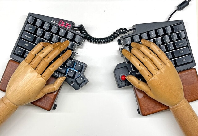
Finally got my @UltHackKeyboard modules. The trackball is perfectly intuitive; now I can get rid of the🖱️ for good 🎉 I don't think any other keyboard out there gets even close to what UHK delivers! Kudos to you @mondalaci 🙇♂️ pic.twitter.com/avV0K9V8SZ
The trackball module is a gamechanger for me. The default red one (which I prefer colourwise) is a little to light for my preferences, but the black one does it for me really well. Great move to provide different balls. Most ppl should be able to pick one that match their liking.
Hi there, and welcome to this monthly UHK status update!
We’ve been churning out as many modules as we could In July and received more feedback than ever, including Yukio Miyamoto’s who happens to be an outstanding illustrator. In his true style, Yukio wasn’t afraid to put his skills to good use, resulting in some spectacular photos.
I’ve recently noticed that our batch allocation algorithm was buggy, and it didn’t respect our first-come, first-served principle. If it did, we would have already shipped every Crowd Supply order. I’ve just fixed our algorithm, and the last Crowd Supply order is expected to leave our facility next Wednesday. Chances are good Crowd Supply will deliver every pending order in August.
We expect to ship non-Crowd Supply module orders in August, too, except for the modules of UHK 60 v2 customers who haven’t ordered a UHK 60 v1. We’ll deliver such modules together with UHK 60 v2 keyboards, as the modules are not helpful without a keyboard.
As for the UHK 60 v2, we received the first production sample of its injection-molded cases just a couple of days earlier.
The cases are the only missing parts to launch UHK 60 v2 production, so this is a major step forward, but they contain some minor defects, and the tooling must be fixed accordingly. We’ll receive subsequent case samples in a week or two, and afterward, the mold may have to be further tweaked depending on the results. We’re pushing hard to launch UHK 60 v2 production in August.
From that point forward, we’ll continuously ship UHK 60 v2 pre-orders on a first-come, first-served basis as quickly as we can. We should be able to ship the majority of UHK 60 v2 preorders in 2021, but some will probably slip to early 2022 despite our best effort. We can’t provide a more precise production schedule yet, but we’ll keep you updated monthly as usual.
Your tweets
We’re delighted to see your posts on the modules and the UHK in general. Please keep spreading the word; we greatly appreciate it.
@UltHackKeyboard Trackpoint and Key Cluster modules just arrived. Plugged them in and they just work! As a longtime ThinkPad user, it is SO great to once again have a trackpoint! Placement feels "natural" and the "thumball" feels good for scrolling. Awesome work! Worth the wait!
— Broadcast Tool & Die (@BroadcastTool) July 28, 2021
Hi there, and welcome to this monthly UHK status update!
Module shipping has peaked in June, and as a result, we’ve received some tweets which make us very excited.
.@UltHackKeyboard I am now fully moduled up! Very impressed with the trackball module especially. It has the same immediate usability and feeling of “how did I manage without this” of the UHK itself! #gotmyuhkpic.twitter.com/lsS2XUWqQl
— Heidi hopes you are ok (@wiredferret) June 21, 2021
Right now, module production is on a temporary halt, and it’ll resume in two days; we recently noticed that a large portion of module cases didn’t meet our quality standards, and we had to get new cases made. This issue set back module production by about one and a half weeks, unfortunately. We’ll be doing more thorough early incoming quality control to catch such problems early on.
We’ll keep churning out the modules, and we expect to ship every Crowd Supply order in the first half of July. The delivery of non-EU orders via Crowd Supply may take weeks longer due to the extra fulfillment and shipping step on their part.
We’ll continue with the modules ordered via the UHK webshop, and we believe we’ll ship most or all of them until the end of July, except for the modules of UHK 60 v2 customers who haven’t ordered a UHK 60 v1. We’ll deliver such modules together with UHK 60 v2 keyboards, as the modules are not helpful without a keyboard.
As for UHK 60 v2 production, we’re only two days away from having the final mold, but our injection molding supplier has an organizational restructuring which can delay the production schedule by about a week or two. When the first molded UHK 60 v2 parts come off the assembly line, we’ll see how much tweaking has to be made to the mold. We believe we can launch UHK 60 v2 production in late July.
From that point forward, we’ll continuously ship UHK 60 v2 pre-orders on a first-come, first-served basis as quickly as we can, possibly until the end of the year. We can’t provide a more precise production schedule yet, but we’ll keep you updated monthly as usual.
We appreciate your patience, and we’re looking forward to talking to you at the end of July.
Hi there, and welcome to this monthly UHK status update!
Module production is in full swing. When we started up, we could only assemble several hundreds of modules per month, and now, it’s in the thousands. We expect to ship every module order in June, excluding customers without a UHK.
It took me a lot of time to sync Crowd Supply orders with our database and tweak our backend system for order fulfillment via Crowd Supply. But now that our systems are ready and we have quite a few modules in our facility ready to be shipped, you can expect a heavy surge of module shipments In June.
If you got your modules, make sure to update to the latest Agent and flash the latest firmware as we keep smashing bugs and releasing new versions.
The modules are not helpful without a keyboard, so UHK 60 v2 customers without a UHK 60 v1 who also ordered modules will receive every item in one package, including their modules and UHKs.
Almost every part is available for UHK 60 v2 production except for keycaps and plastic parts. Our PBT keycap supplier confirmed that they’ll start shipping keycaps in mid-June, as previously discussed, and the silk-printed side legends of the final PBT keycap sample look great.
As for the plastic parts, tweaking the plastic module cases pushed UHK 60 v2 plastic part production further. As a result, we expect to launch the production of the much-anticipated UHK 60 v2 units in early July.
From that point forward, we’ll continuously ship UHK 60 v2 pre-orders as fast as we can, possibly until the end of the year. I asked our plastic supplier to hurry up without compromising quality.
The best way forward is to plow through every obstacle we encounter, and I’m sure we’ll end up with a keyboard like no other. We appreciate your patience on this journey, and we’re looking forward to talking to you at the end of June.
Hi there, and welcome to this monthly UHK status update!
TL;DR: The first 400 modules have been shipped from our facility, and we’ll be continuously shipping the remaining module pre-orders. We’ve approved the latest PBT keycap set our supplier sent to us, and UHK 60 v2 production is expected to start in early June. We will try to provide estimates regarding pending orders in our next update.
Also, please open the web address that you can find in the module boxes to be able to use the modules and make the most out of them. Don’t forget to update to Agent 1.5.12 and firmware 8.10.9 or any later version available.
Production progress
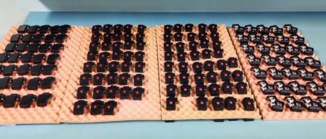
After all this time, we’ve finally shipped the first module batch, containing 400 modules. These are some of the modules.
We’ve ended up providing a red ball, a black ball, and a steel ball for the trackball modules because we’re unsure which one you’ll like best, and your feedback is much welcome.
We can’t wait to see your posts and hear your experiences regarding the modules. The following is the first we’ve received.
You may be wondering why you haven’t gotten your module order even though you ordered earlier than Domi. The reason is that so far, we’ve only shipped non-Crowd Supply module orders because Crowd Supply’s order database is not synchronized with ours yet. In a couple of days, however, it will be synchronized, at which point we’ll start shipping Crowd Supply module orders, too.
We’ll be continuously shipping the remaining module pre-orders in the coming months. We’ll provide an estimate regarding module shipping, but it’s too early as it was challenging to start module mass production, so the assembly speed of the first module batch is not representative.
As stated in our previous newsletter, the UHK 60 v2 is currently blocked by the lack of PBT keycaps and plastic parts. Our keycap supplier expects to start shipping the keycaps in early June, by which time the plastic parts should be ready, too, and UHK 60 v2 production will begin. From that point forward, we’ll continuously ship UHK 60 v2 orders, possibly until the end of the year, which begs some explanation.
The current and future state of delivery
Under normal circumstances, we ship orders in a matter of days, as we did from 2019 May to 2020 October.
As you can probably tell, the current circumstances are everything but normal for several reasons, some of which I’m about to explain.
We’re releasing five different products (four modules and the UHK 60 v2). Every product has its own set of manufacturing challenges, and ramping up production is quite challenging even for a single product.
We have quite a backlog, especially of modules that we need to fulfill. At the same time, the demand for our products has significantly increased recently.
Our on-site, on-demand manufacturing operation is excellent when it comes to a steady stream of orders but not ideal for combating large backlogs. As a result, it takes more time to catch up than if we had an OEM in China.
The electronics supply chain is a wreck due to Covid. We had to purchase several thousand ICs for the modules and the UHK 60 v2 for about ten times the price we usually pay, and we were told we’re lucky we could even get the parts.
We sympathize with every one of our customers whose order is delayed, and we’re doing our best to catch up.
If you need an ergonomic keyboard quickly due to health issues, the UHK is not the right choice now. (Unless you pick up the handful of UHK 60 v1’s left on stock.) But if you’re not in a hurry, it’s still worth purchasing because we’ll raise the price of our products after we catch up with pre-orders, and we deliver on a first-come, first-served basis.
On the upside, after shipping the current module and UHK 60 v2 pre-orders, we expect to ship most orders in 24 hours on workdays, faster than ever before.
Thanks for your understanding, and your continued patience is much appreciated.
Your tweets
Please keep spreading the word on the modules and the UHK in general. The following tweets put smiles on our faces.
In case you missed it on Saturday, I have a blog again, and the first real post was about my workplace setup - maybe it helps the one or other among you!