Hi there, and welcome to the monthly UHK status update!
TL;DR: We expect to start shipping the modules in July, and we’re making rapid progress.
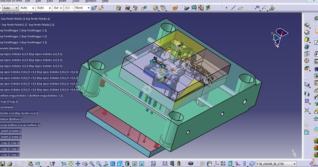
As mentioned in our previous monthly update, there are a number of tasks to be done to mass produce the modules, but the most time consuming of all is the creation of their molds. The good news is that our mold making supplier just provided us an ETA: June 2020. This means that we should be able to begin shipping orders in July, likely completing all orders in August.
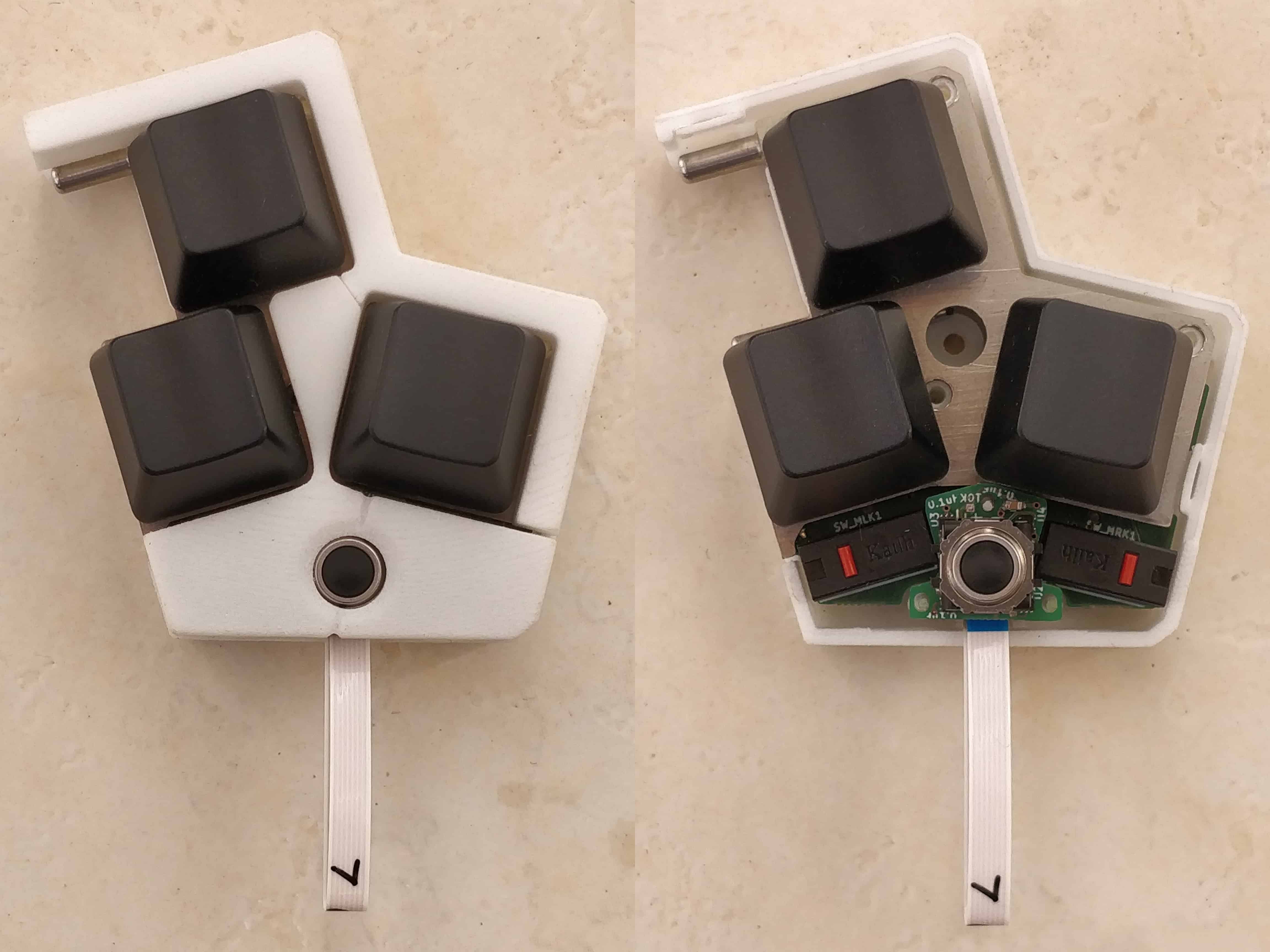
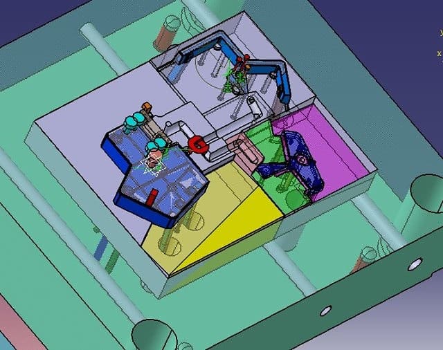
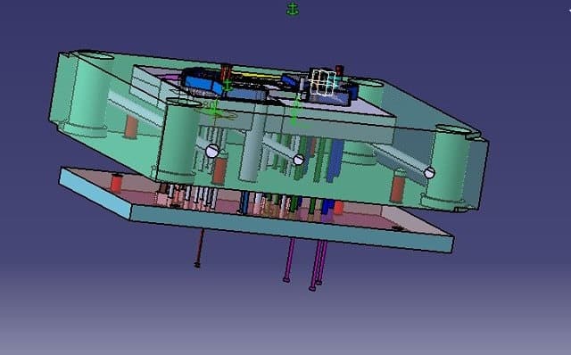
Our supplier is almost ready with the design of the key cluster module mold:
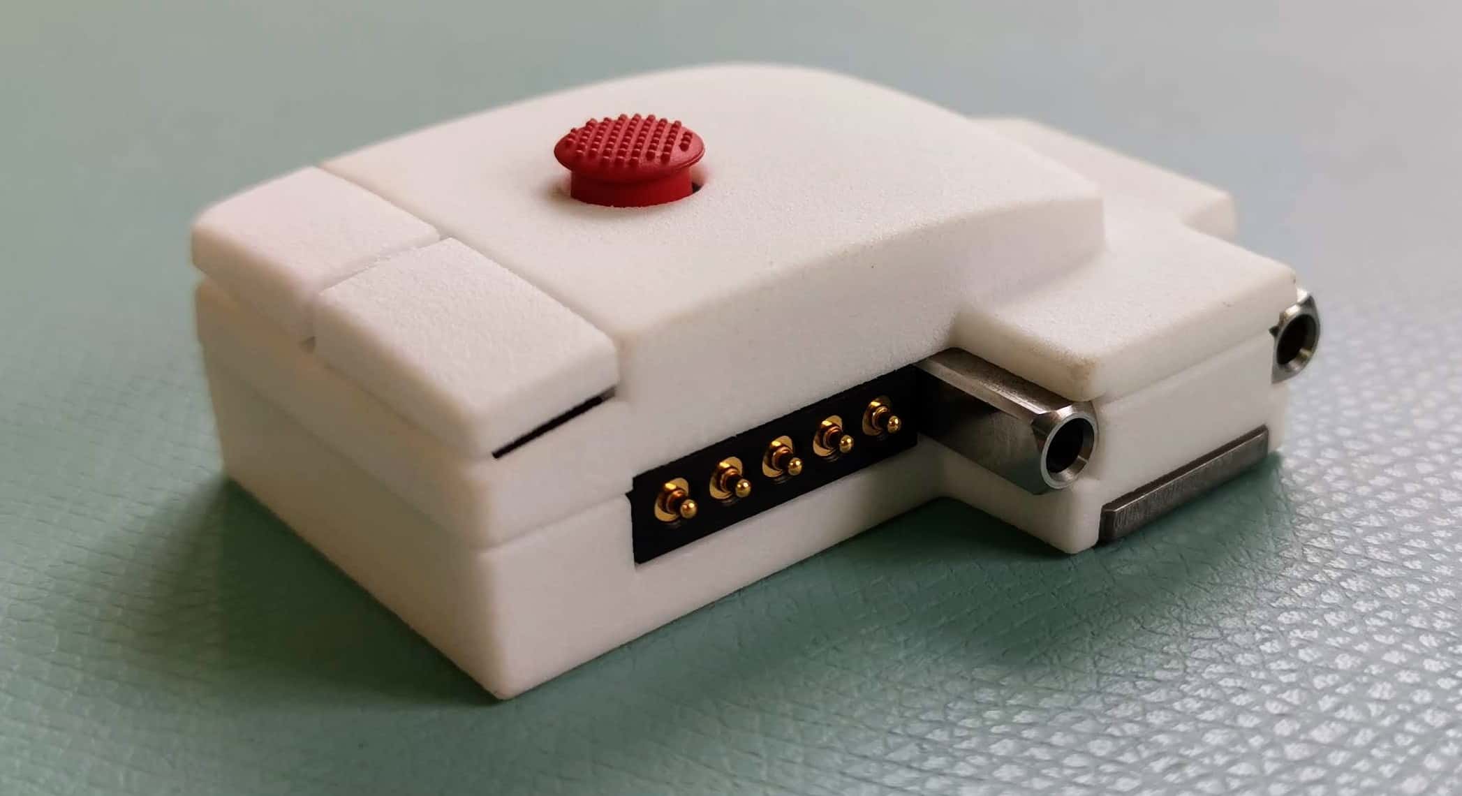
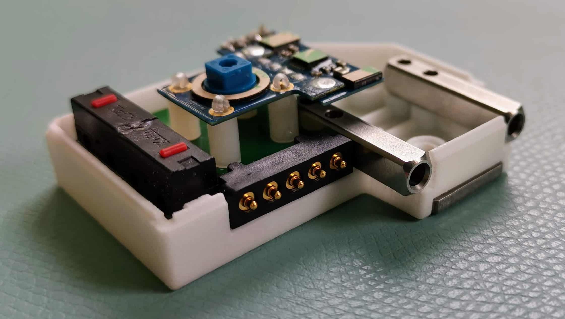
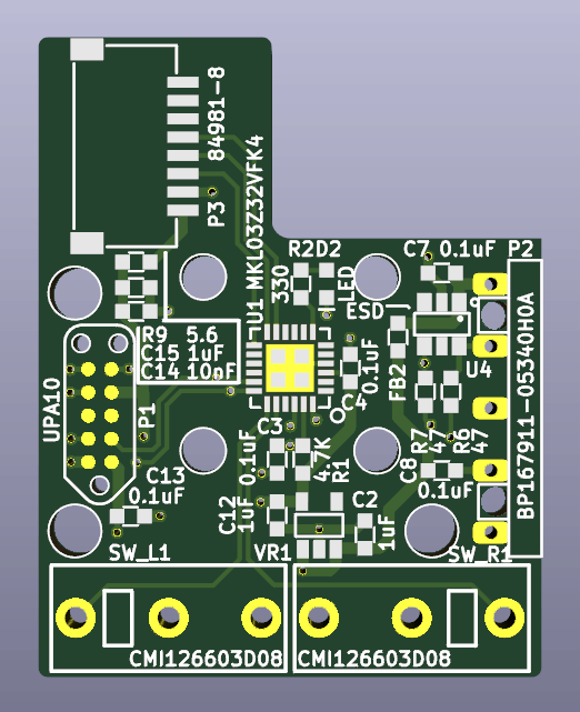
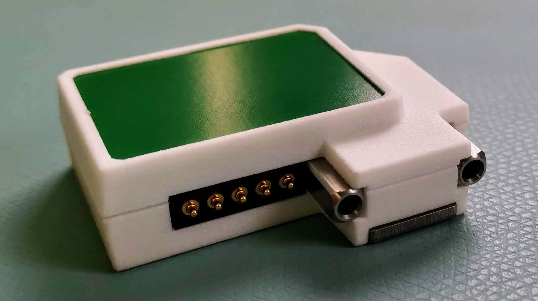
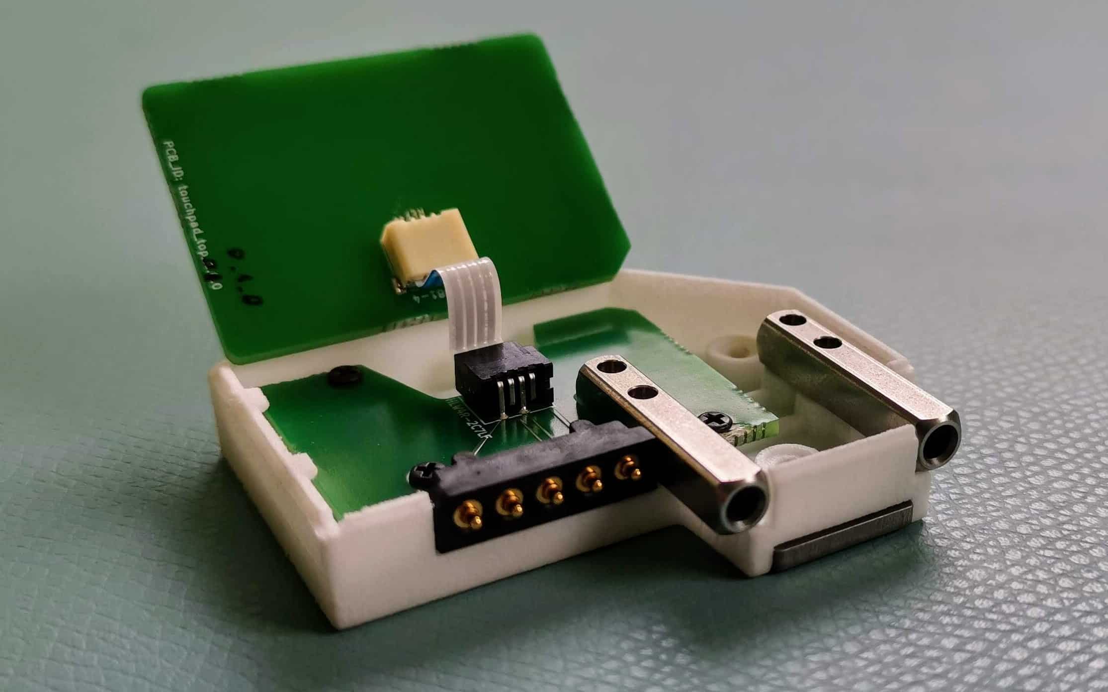
András has been working a lot on the 3D models of the modules recently, and all the modules should be finalized soon.
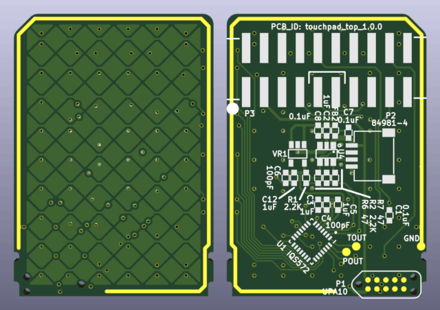
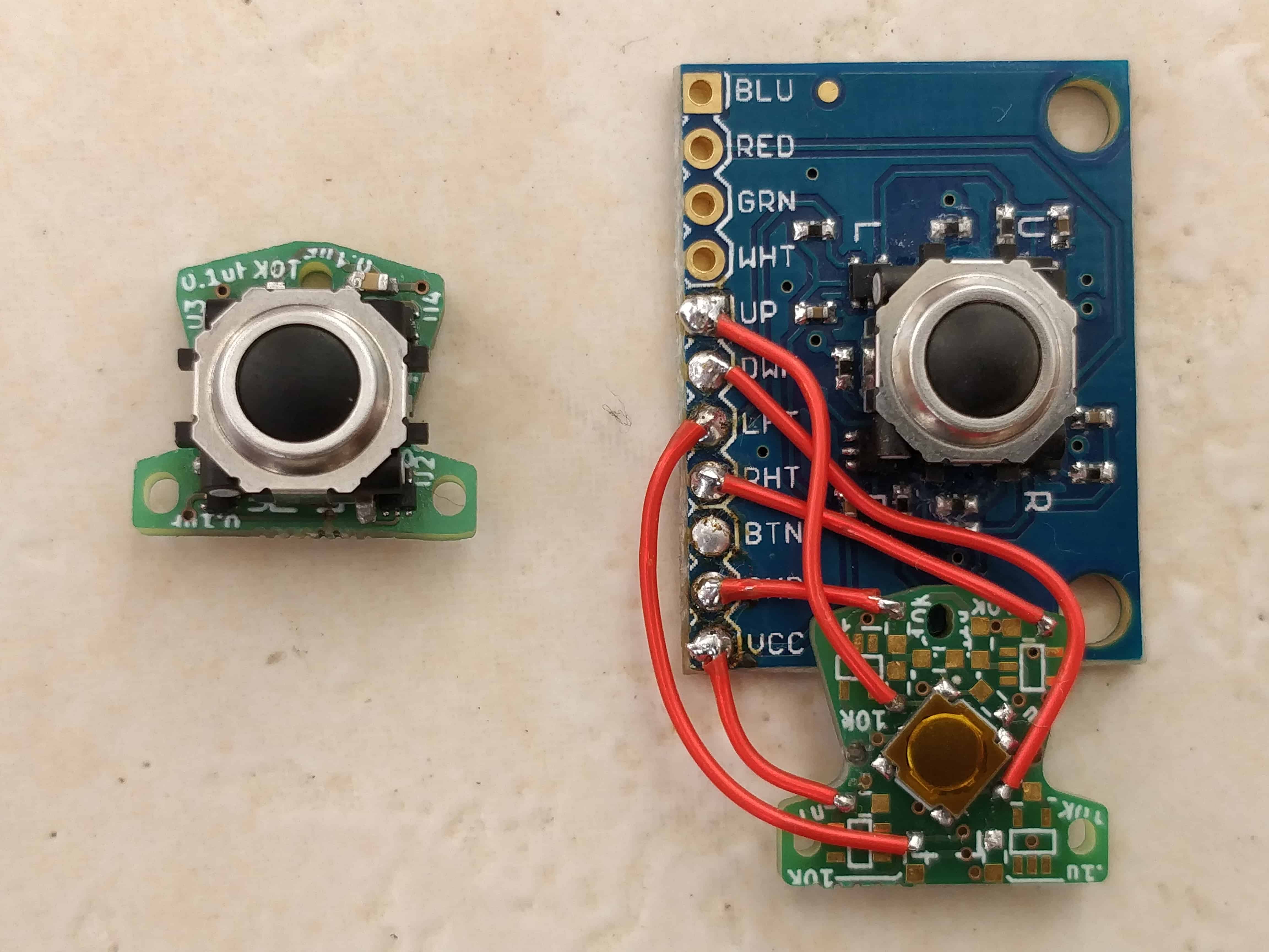
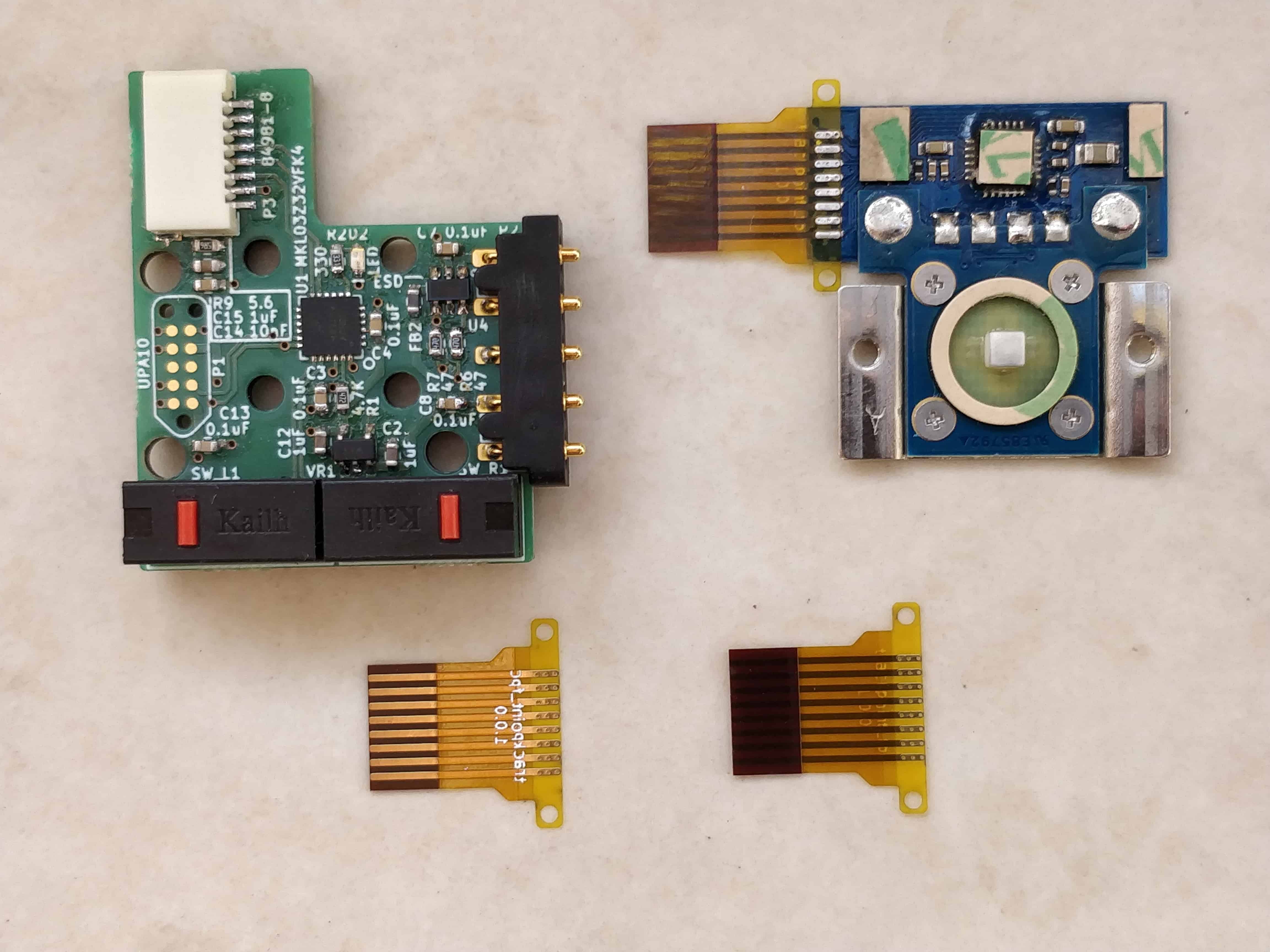
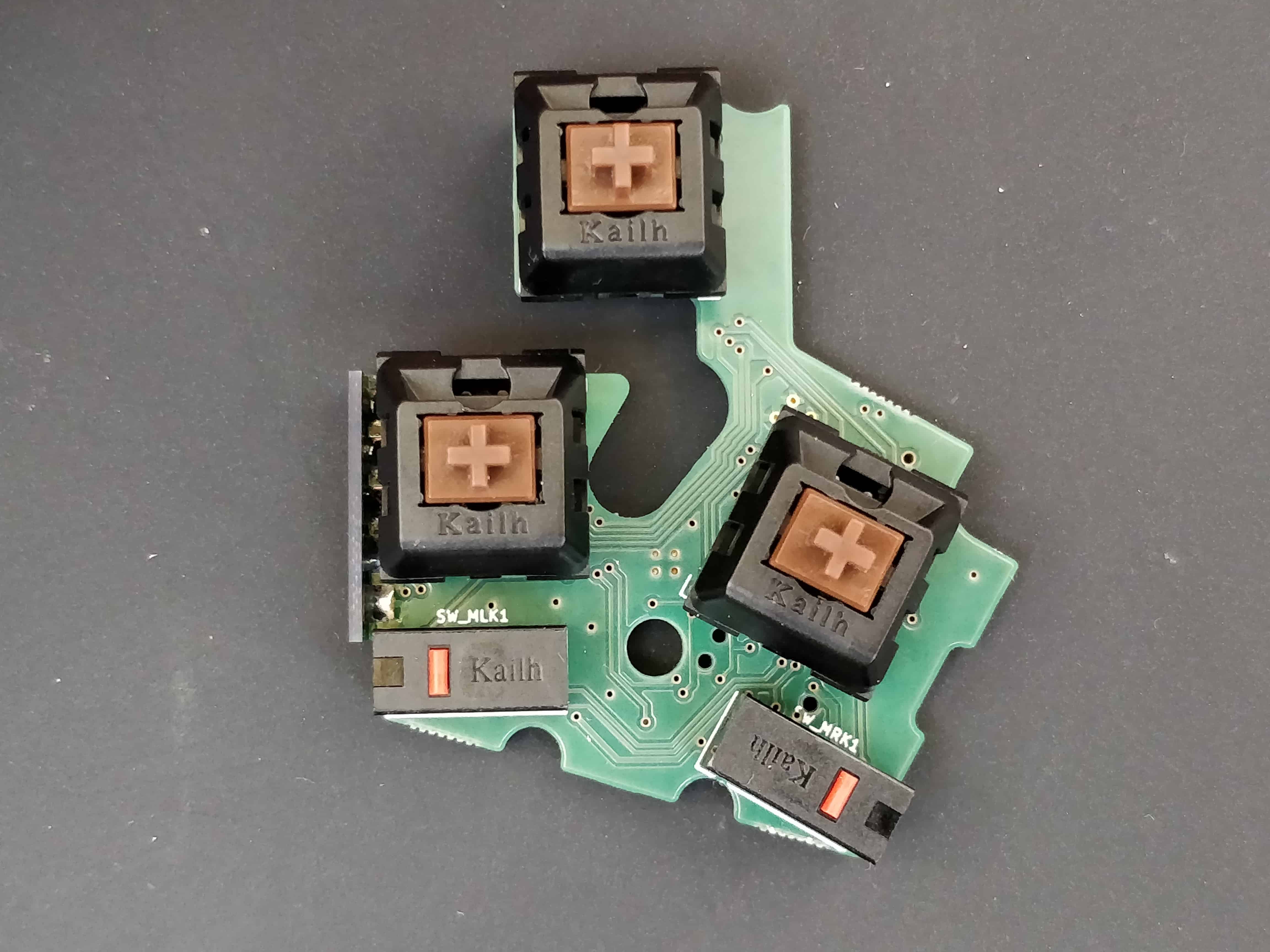
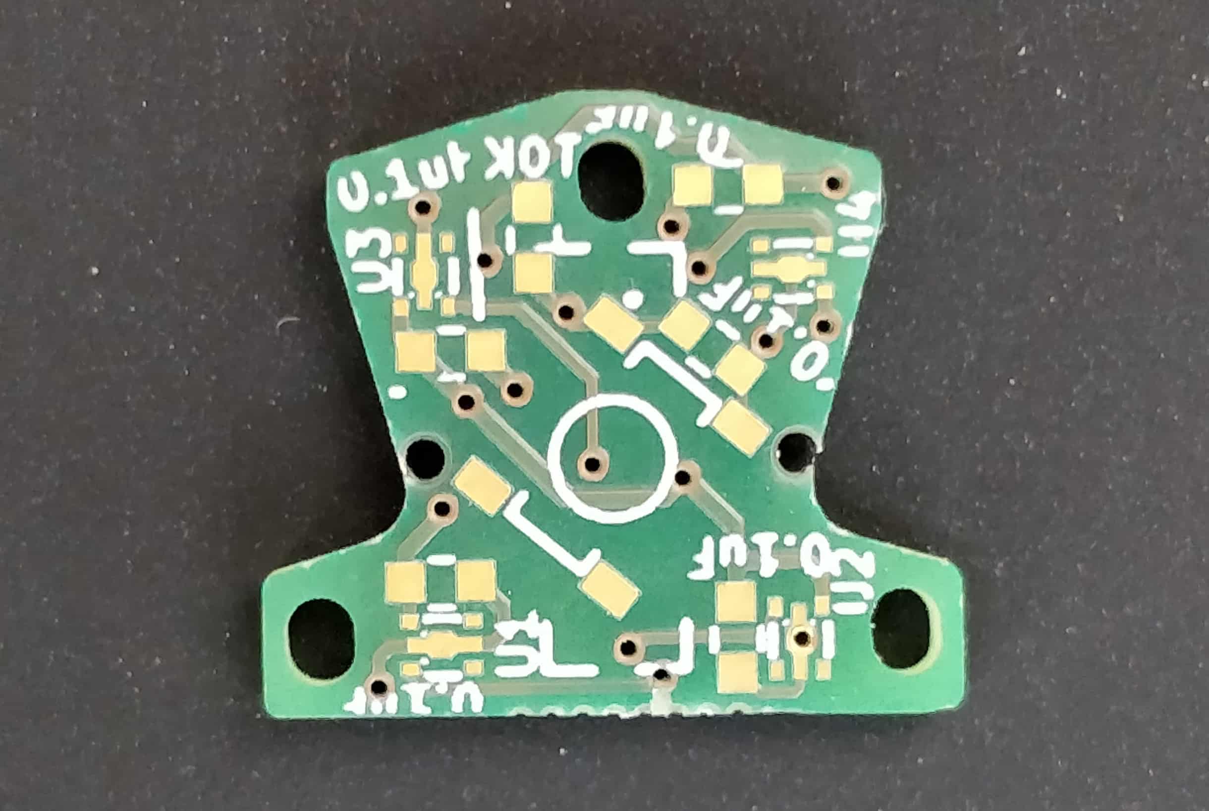
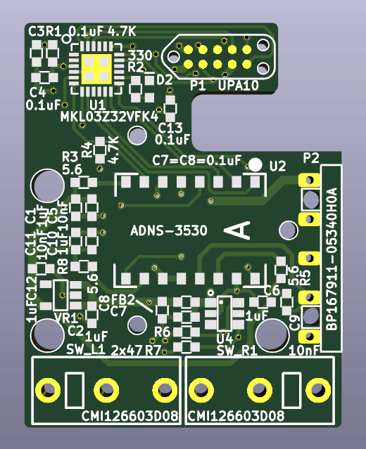
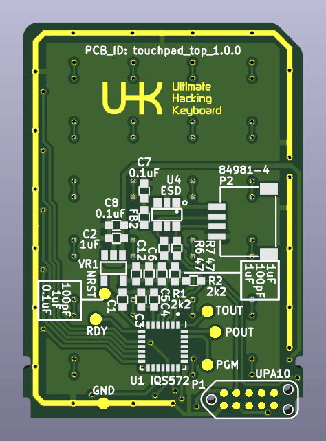
In the meantime, I’ve been busy optimizing the PCBs of the modules for manufacturing. It’s not rocket science, but there are a ton of details involved, and small tweaks can go a long way.
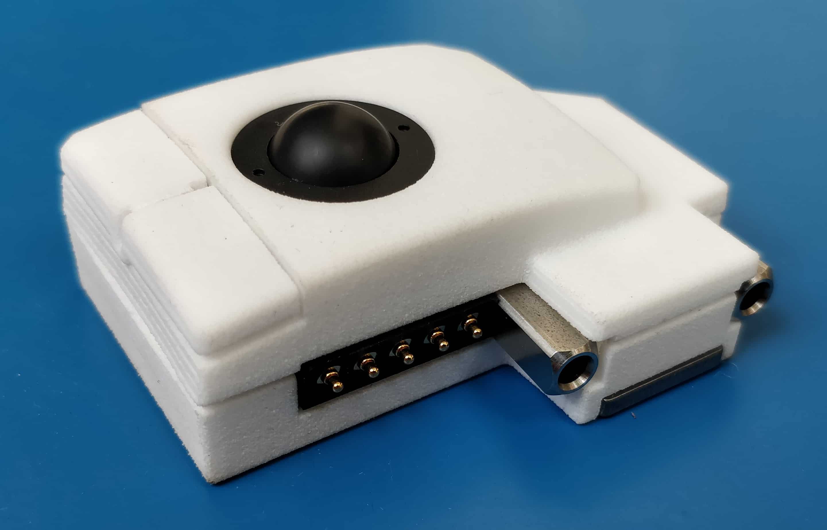
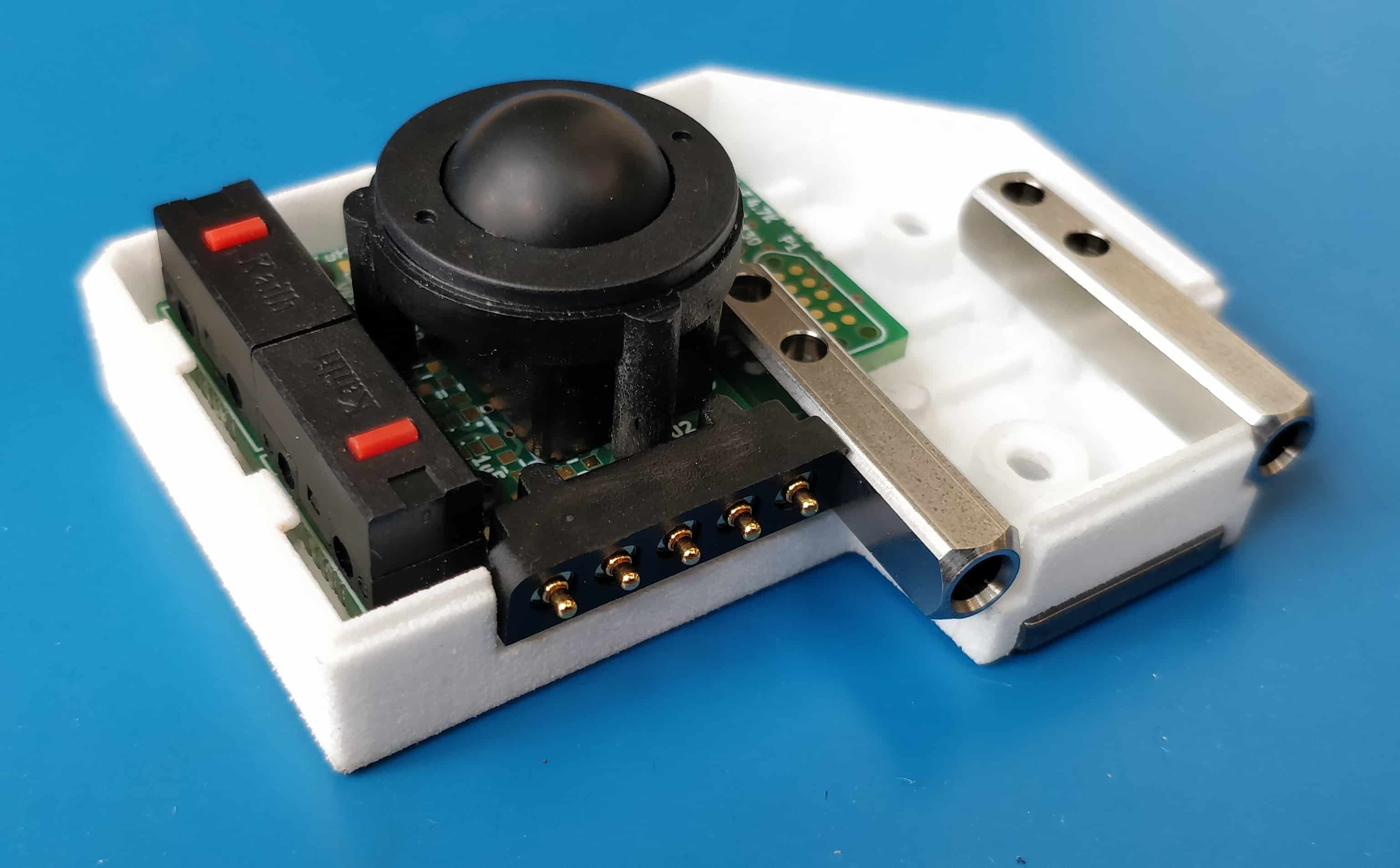
We’ve also started the procurement of the parts for the modules. Most of them are not very urgent, but there are exceptions like the optical sensor of the trackball module which can take up to 14 weeks to arrive. Luckily, we’re just in time to hit our ETA.
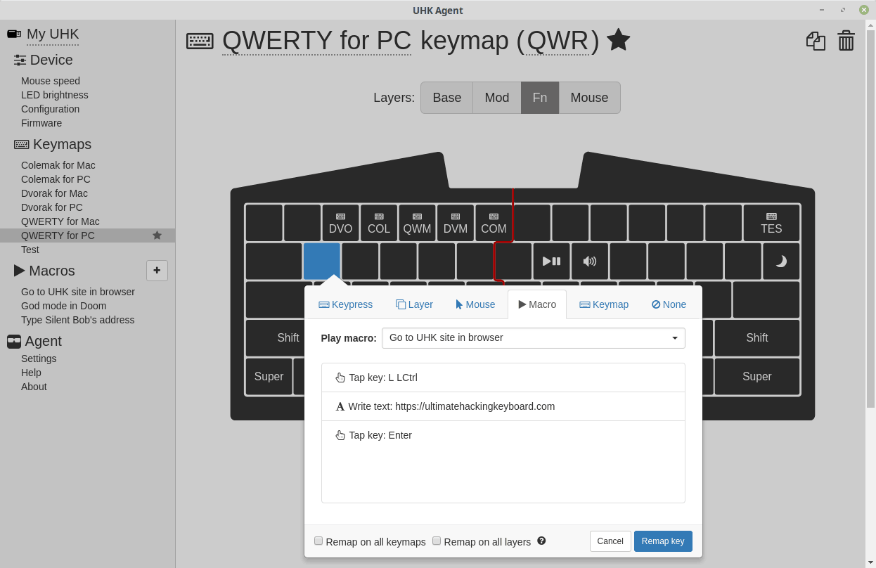
We’re knee deep into getting the modules manufactured, everything is going well, and we’ll be keeping you updated on a monthly basis as usual. You can change your shipping address any time.
UHK ninja belt
Special shootout goes to Hubert Łępicki who amused us with his UHK ninja belt (for the lack of a better term).
Nobody:
— Hubert Łępicki (@hubertlepicki) March 4, 2020
Me: pic.twitter.com/wR8CexCiIS
Hubert wouldn’t be a true ninja without demonstrating his belt in action. Check out the following video.
Nobody:
— Hubert Łępicki (@hubertlepicki) March 5, 2020
Me: pic.twitter.com/mQX3j8qtwv
3rd party keycap sets
Some of you are on a never ending journey of pimping up your UHKs, and we’re excited to see your creations!
I #GotMyUHK from @UltHackKeyboard over a year ago and decided it needed some new key caps. I opted for the SA 1976 set from #pimpmykeyboard pic.twitter.com/8hkesv01m9
— John Derr (@johnderrdotnet) February 20, 2020
Semi final form of my @UltHackKeyboard ... still looking for the GMK Oblivion spacekit. pic.twitter.com/EuNEvfPAaM
— Rakan Alhneiti (@rakanalh) March 5, 2020
Further tweets
You guys keep sending your awesome tweets, and we're always eager to read and feature them! If you got your UHK, please share your love!
Didn't think I would actually say this, but after using my @UltHackKeyboard for a while, it's actually hard to go back to regular keyboards. Still getting used to it, but it's helped my tendinitis much, and it's so nice to be able to program all the keys easily.
— Trevor (@chivsjawn) March 10, 2020
I #GotMyUHK it‘s awesome 😎 .@UltHackKeyboard pic.twitter.com/C9exeXZmpz
— Oguz KAYA (@asyetisbey) February 20, 2020
Split keyboards are extra portable. Thanks @UltHackKeyboard pic.twitter.com/N6uIuKlXHM
— Neil H. Watson (@neil_h_watson) February 19, 2020
We’ll be keeping you updated on all things UHK, and are looking forward to talking to you on 2020-04-10.