This is a short update to let you know that new orders ship in a week. If you ever wanted to buy your UHK but were afraid of the historically long shipping delays, fear no more as we finally have stock.
And if you got your UHK, tweet about it, or it didn’t happen! We’re always delighted to hear about Ultimate Hackers as they receive their orders.
Wanted to come back after using it for a few months and say that the @UltHackKeyboard kicks absolute ass. My back and RSI aches and pains have been way better, often nonexistent, and it makes editing in particular go so much faster never having to lift my hands to use the mouse. pic.twitter.com/eKZFbXKYaI
Ultimate Hackers rejoice; we have a forum! Feel free to sign up and mingle, even if you're not single.
Asking for a forum has been a recurring theme among the community, and understandably so, as there are countless ways to configure the UHK, especially with the introduction of smart macros that open up a new world of possibilities. Twitter doesn't cut it for long, thoughtful discussions.
We needed a forum with outstanding usability that supports easy-to-follow, thematic conversations. Given these criteria, the choice was obvious to me: Discourse.
Discourse is an open-source forum engine made by the community for the community. I've been participating in many Discourse forums, and my experience has been exceptionally frictionless; Discourse is designed extremely well from the inside out.
I've recently taken some time to set up a self-hosted Discourse instance, then tweaked it a bit. Members started to flock in, and it's becoming quite a buzzy place, even unannounced.
What is the UHK forum about?
This forum is about all things UHK, except:
Customer support – Please submit your issue via our contact page instead.
Sales – If you want to sell your UHK, please use r/mechmarket?q=uhk or another marketplace, as we prefer to make the forum a useful source of information about the UHK, not a marketplace.
Based on the current threads, most members are looking for advice regarding configuration settings, and quite frankly, we could use some help from experienced users answering these questions. Still, regardless of what you're interested in, you're welcome to join.
I hope you'll enjoy the forum. Let's be excellent with each other, and we'll see you there!
TL;DR: We've just released the UHK 60 v1 backlight upgrade kit, containing keycaps, LEDs, and a keycap puller. Soldering is needed to install the LEDs.
Ages ago, we promised to release the backlight upgrade kit for the UHK 60 v1. In the meantime, we've been busy releasing the modules, the UHK 60 v2, and catching up with production amid Covid and the chip shortage. But now that we've caught up, it's time to release the kit, so let's discuss the details.
On the bright side, pun clearly intended, the sides of the keycaps are also lit, not just their top side. As a matter of fact, the backlighting of the sides is more consistent than the top sides.
On the flip side, these keycaps are laser-etched ABS keycaps that may last years but won't last forever, and the black paint may wear off eventually. We plan only to use PBT keycaps going forward, but this kit is such a niche product, even for us, that it didn't make financial sense to pay for the tooling of custom PBT keycaps. (The UHK 60 v2 PBT keycaps are not recommended to be used with this kit because UHK 60 v1 LEDs are located at the bottom of the keycaps versus the UHK 60 v2 LEDs, which are located at the top.)
The kit contains keycaps for both ANSI and ISO UHKs, and it doesn't contain Mac and Windows keys, only Super keys.
The UHK 60 v1 only supports single-color backlighting. Namely, we provide white LEDs, and you have to solder them. Soldering is quite time-consuming, so we don't offer a soldering service but provide installation instructions.
Thank you for reading this short announcement. We hope we put a smile on the faces of some UHK 60 v1 owners. Talk to you later!
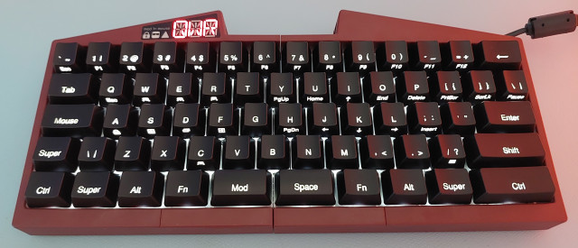
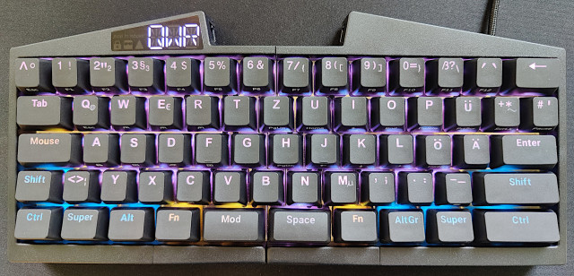
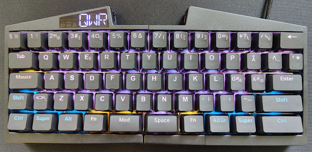
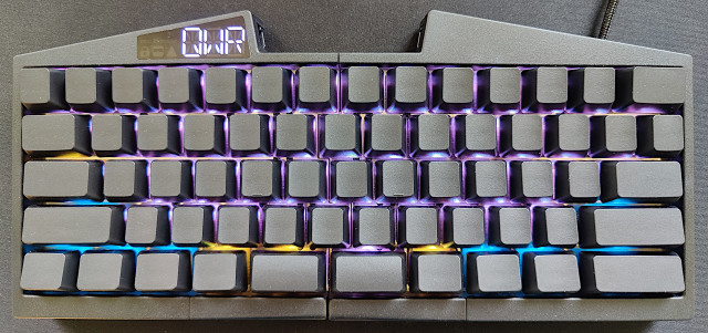
Hallo, hallå, and hei! We're excited to introduce new PBT keycaps, including:
German,
Nordic,
Plain ANSI and ISO (just like the Blank option, but without the dots),
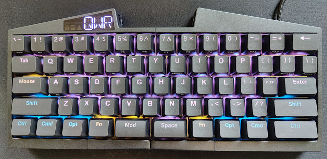
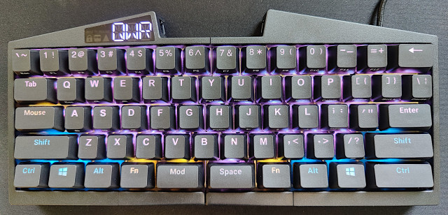
OS keycaps include two Cmd, Opt, and Windows keycaps to make you feel more at home if you're a Mac or Windows user.
Let me emphasize that these are not cheap ABS but durable PBT keycaps. PBT keycaps featuring non-English symbols are rare, and we've paid dearly for their tooling to bring them to life. These keycaps are backlit-friendly, the same type that the UHK 60 v2 has. The legends are easy to read even when they’re not backlit. The surface of these keycaps never gets shiny with use, and their legends never fade.
The OS keycaps are only available as a separate product. We won't make them available as a product option for the UHK because we already offer too many product options, which makes manufacturing slow and error-prone.
Let's see some photos of the new keycaps in their full glory.
GermanNordicPlain ANSIOS keycaps: MacOS keycaps: Windows
We haven't forgotten about the UHK 60 v1 backlight upgrade kit that we promised ages ago, and we'll announce it in a separate update.
Lastly, I'm delighted to say that we've caught up with pending orders, and new orders will ship in a week.
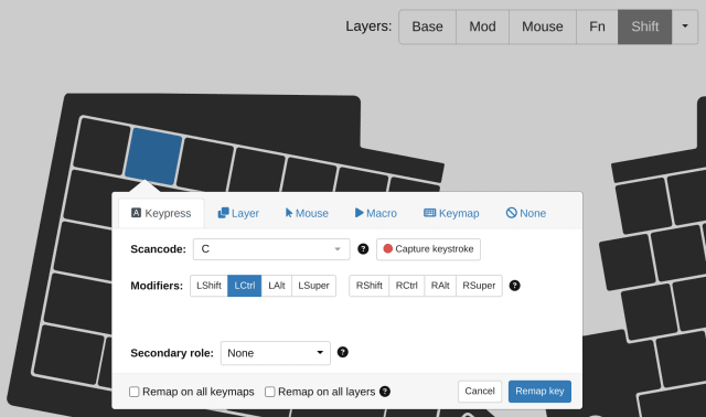
The modifier layer (in this example, the Shift layer) automatically becomes active when you press the relevant modifier key. If a key on the modifier layer is unmapped, the UHK will fall back to the base layer and compose its mapping with the modifier.
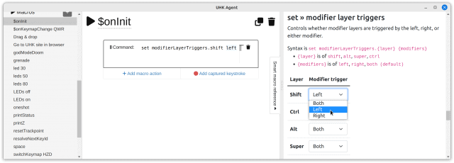
You're probably already done, but there's one more thing. By default, modifier layers can be activated by both left and right modifiers. If you want to use only the left or right modifier to activate a modifier layer, you can change the modifier layer triggers via smart macros:
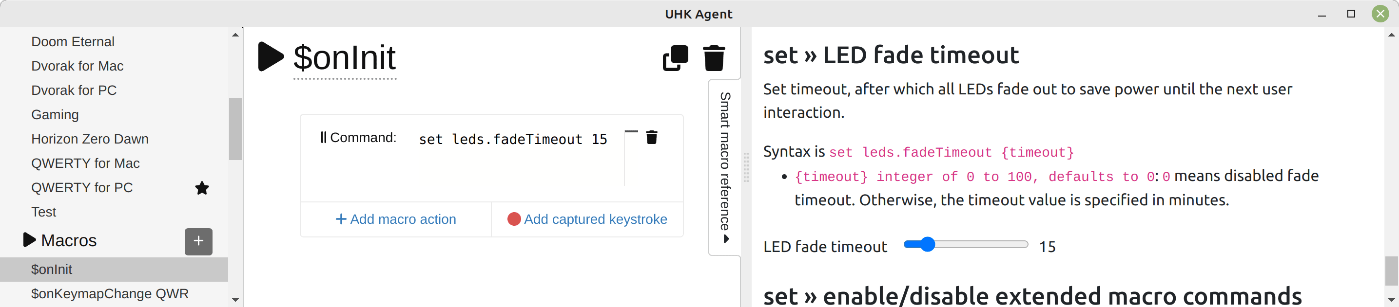
Update 2023-08-19: Now the "LED settings" page contains the "LED fade timeout" setting, so you don't have to use smart macros to use it.
Some of you want your UHK to automatically turn off its LEDs after some idle time, which can be configured by setting the leds.fadeTimeout smart macro variable in the $onInit macro as follows.
Hi there, and welcome to this short and slightly late monthly UHK update!
We've created a survey that you're welcome to fill out regardless of whether you have a UHK. You can directly affect the development of the UHK and the creation of new models this way.
Speaking of manufacturing progress, we've almost caught up, as the oldest pending order is about a week old. Unfortunately, we're out of palm rests again, but luckily, we'll get a new palm rest batch about two weeks later, and we'll fully catch up with orders then. Consequently, we expect new orders to ship in about three weeks. We'll keep you updated via the delivery status page.
If you got your UHK, tweet about it, or it didn’t happen!
Happy new year, and welcome to this short monthly UHK status update!
We have assembled all pending orders, but we can't ship the ones that include palm rests because we'll only receive palm rests in January in multiple small batches. We plan to ship every pending order in January, and we'll update the delivery status page every weekend.
Please note that we can't make partial shipments for orders that contain palm rests. We appreciate your patience!
We’re delighted to hear from UHK 60 v2 customers as they receive their orders. If you got your UHK, tweet about it, or it didn’t happen!
Finally. I cannot hide my joy. Build quality is top of top. Layout change is magical. Blank ISO + Box White key switch + Key Cluster module + Trackball Module. Assisted by Magic Trackpad. @UltHackKeyboardpic.twitter.com/g4rGmZ8bg7
TL;DR: Say hi to 12 layers per keymap, module speed and acceleration settings, and loads of advanced features, mostly enabled by the new smart macros functionality of the latest UHK Agent and firmware releases.
I don’t usually write dedicated posts about new releases, but this is a major one, we’ve been working on it for a year, and it delivers a huge punch that can elevate your UHK experience to the next level, so it mustn’t go unnoticed.
A summary of new features to whet your appetite:
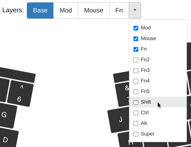
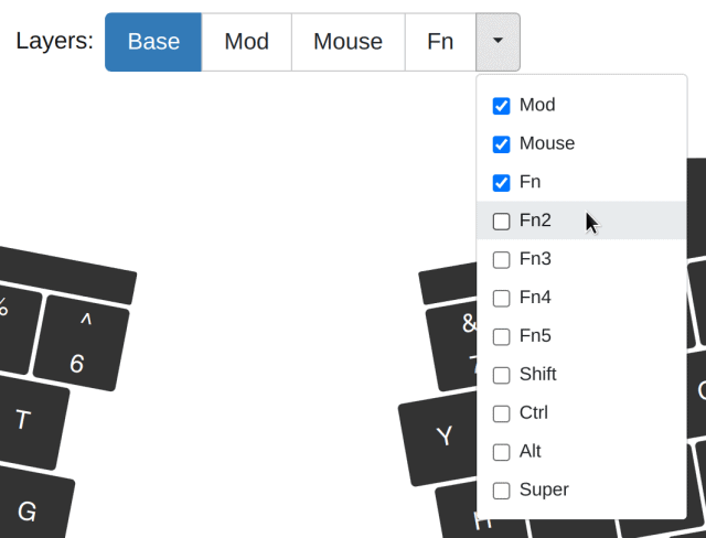
Extended the original four layers per keymap with four regular layers (Fn2, Fn3, Fn4, Fn5) and four modifier layers (Shift, Ctrl, Alt, Super).
All modules: speed and acceleration settings, axis locking settings, per-layer navigation modes
Key cluster module: Added the ability to fine-tune or disable the behavior of the mini trackball.
Trackpoint module: Fixed occasional trackpoint pointer jumps and made it easy to stop drifting if it occurred.
Touchpad module: Implemented pinch-to-zoom, two-finger scrolling, doubletap-to-drag, and made the tap action configurable.
Advanced configuration scenarios via smart macros, such as configurable modifier layer triggers, mouse key axis skew, and LED fade timeout
Super-advanced configuration scenarios via extended macro commands, such as variables, loops, double tap actions, and runtime macro recording.
Implemented N-key rollover.
Made accelerate and decelerate actions work with modules.
Fixed USB descriptors which caused high CPU load on Macintosh computers.
Let’s go over the main features, but first, install the new Agent. Then it’ll upgrade your UHK to the new firmware.
12 layers per keymap
Instead of 4 layers, you can now have 12 layers per keymap.
You can enable/disable any of the above layers per keymap except for the base layer, which is mandatory.
The Fn2, Fn3, Fn4, and Fn5 layers work just like the existing layers, but Shift, Ctrl, Alt, and Super are modifier layers.
On modifier layers, you can map alternative actions per key, which trigger when the key is pressed with the relevant modifier. For example, now you can implement the Programmer Dvorak layout solely on the UHK.
You’re probably already familiar with regular macros, which are a sequence of macro actions, such as keypresses and mouse movements.
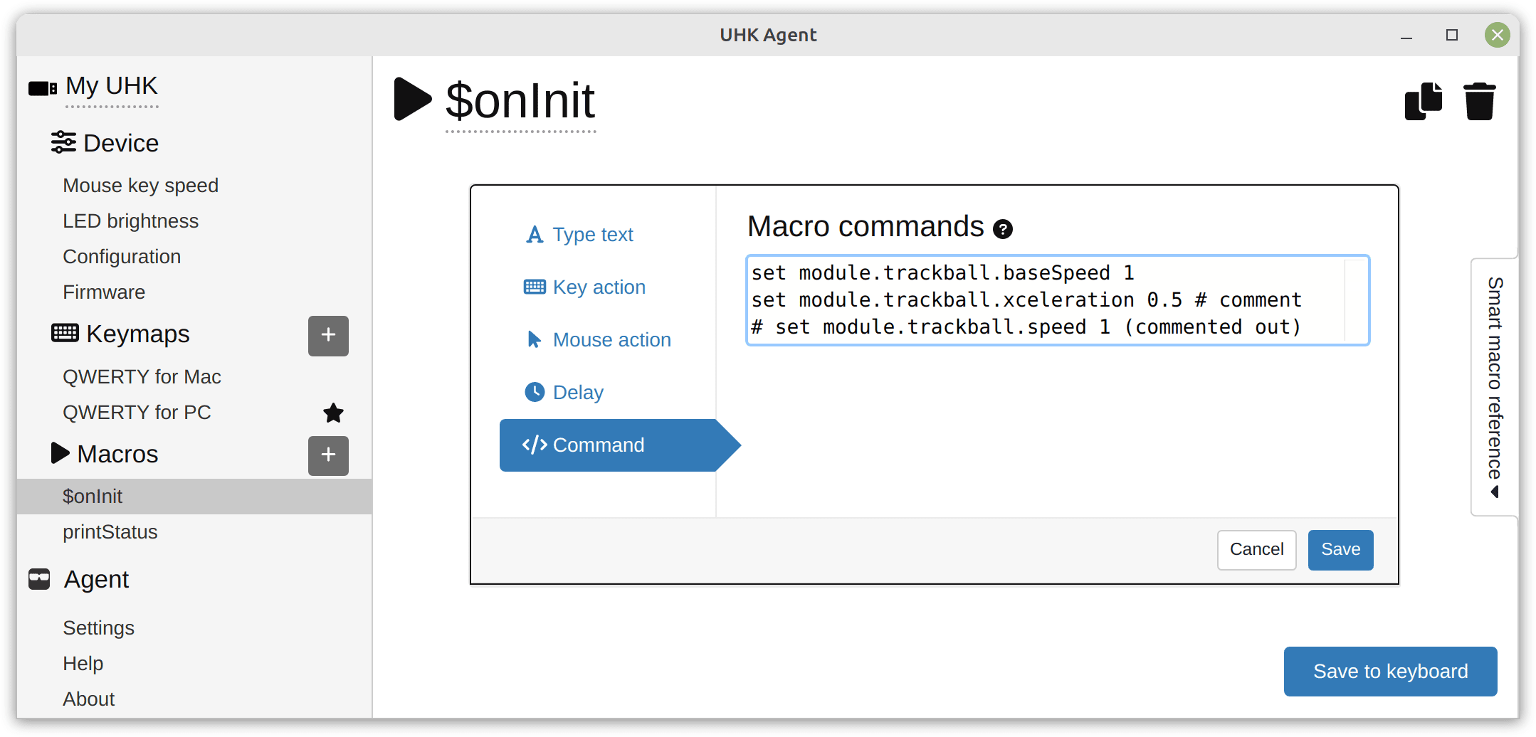
Smart macros, however, enable the advanced customization of your UHK and its modules. See the following screenshot, which shows a macro named $onInit containing a command macro action that contains multiple macro commands:
$onInit is a special macro name. It's a macro event that executes each time your UHK gets powered and when you save its configuration.
"set module.trackball.baseSpeed 1" is a macro command that sets the base speed of the trackball module to 1.
Macro commands work in any macros, not only in macro events, and you can bind them to any key. This way, you can make Fn+1 set your trackball base speed to 1, and make Fn+2 set it to 2, for example.
Interactive smart macro editing
Adjusting values by editing text is tedious. This is why we created a smart macro sidebar that can be opened on macro pages. This sidebar contains easy-to-read documentation and provides interactive widgets that make configuration a breeze.
When clicking on a macro command action, the widgets of the smart macro sidebar display the actual values of the commands, and module-specific widgets appear. You just have to interact with these widgets, hit the usual “Save to keyboard” button, and your settings will be applied immediately.
I strongly recommend you delve into these settings, as they can make a huge difference. The default sensitivity settings of the modules are reasonable, but by tweaking them to your needs, you can make them so much more usable. Maybe, just maybe, you can finally get rid of your mouse.
Advanced configuration scenarios
Besides $onInit, there’s also the “$onKeymapChange {keymapId}” macro event, such as $onKeymapChange QWR, which is executed when the QWR keymap is activated.
This event enables you to have keymap-specific settings, which allows for many advanced use cases. For example, different operating systems have different mouse sensitivity. This feature allows you to have different speed and acceleration settings for your mouse keys and modules via different operating system-specific keymaps.
Believe it or not, I’m still scratching the surface. If you really want to go crazy, you can use the set "macroEngine.extendedCommands 1" command to enable the extended macro engine, allowing for variables, loops, and countless advanced commands. If you’re comfortable with delving into manual pages, check out the extended macro engine user guide and reference manual.
Karel wanted special firmware features, and he originally (ab)used the text macro actions of Agent by making the firmware interpret the lines starting with the $ character as special commands. He’s essentially implemented a command interpreter in the UHK firmware that allowed for his advanced use cases.
I saw his efforts early on, and I was impressed, but I considered his work quite niche and wasn’t too interested. (In retrospect, I can see that his advanced commands are used and loved by many.)
Then it struck me that smart macros could enable the configuration of many UHK and module features without developing Agent, which is a huge win, as adding new features both to Agent and the firmware takes a ton of work. Exposing new features only via the macro engine of the firmware is so much easier.
I came up with the idea of macro events and making smart macros a first-class citizen in Agent, then implemented the smart macro sidebar. Karel has implemented the acceleration driver of the modules, macro events, and, nowadays, pretty much everything that has to be done with firmware logic. His work is hard to overstate.
As an interesting trivia, the macro command editor of Agent might feel familiar. This is because we use Monaco editor, which also powers Visual Studio Code. In a way, Agent became an integrated development environment, supporting a special keyboard language whose interpreter runs in the UHK firmware.
The future of smart macros
I eventually want to expose basic smart macro settings, such as module settings or the LED fade timeout, not only via the smart macro sidebar but dedicated Agent widgets for better usability.
Nonetheless, we’ll keep and extend the currently available smart macro commands and settings because they allow for advanced configuration scenarios.
I plan to gradually move the extended macro commands from the current markdown macro documentation into the smart macro sidebar of Agent to make them easier to digest and not hide them behind the set "macroEngine.extendedCommands 1" command.
Closing words
To this day, we’ve released 60 Agent versions and 66 firmware versions, and we’re still going strong. I’m excited about our progress and grateful to our wonderful customers for their support. We keep moving forward because of you.
Thank you for reading this update! As usual, we plan to publish a manufacturing update around the end of the month. Stay safe!