Hi there, and welcome to this delayed monthly UHK status update!
TL; DR: The assembly of the first 400 modules is underway in our facility, and we expect to ship them in about a week. Afterward, we’ll be continuously producing and shipping module preorders as quickly as we can. One of our key contractors has become suddenly overloaded, and as a result, we expect to start UHK 60 v2 production around the end of April. There are a lot of cool demos in this update, so make sure to read it.
Module production
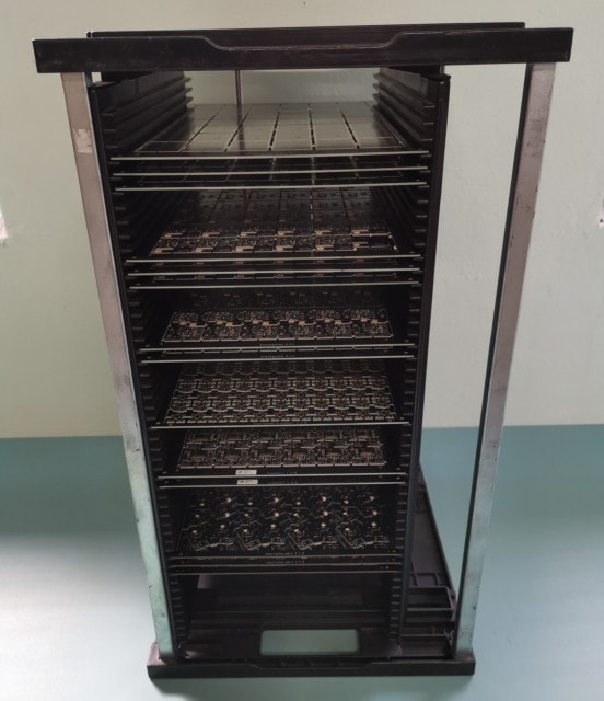
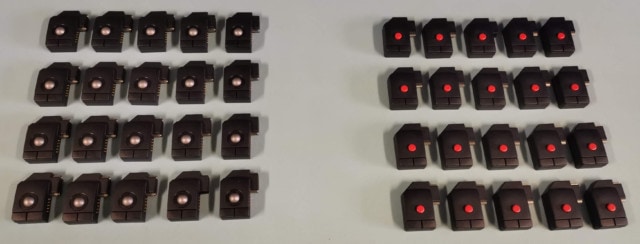
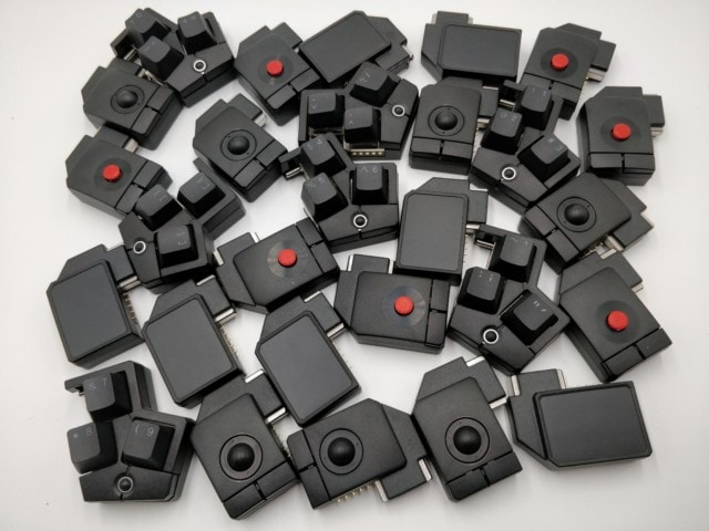
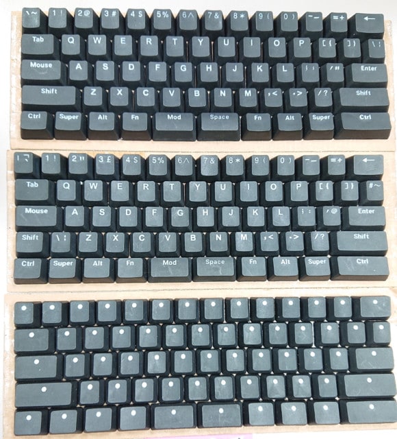
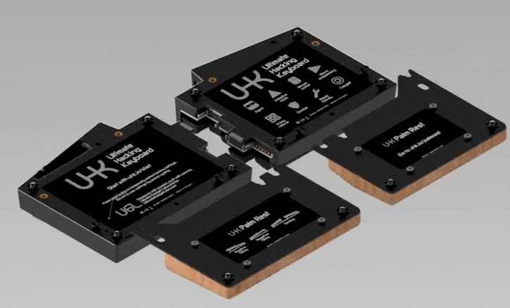
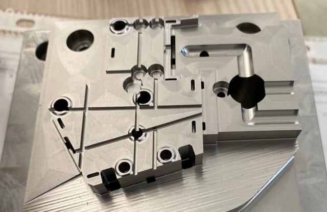
Module manufacturing has finally started, and we’re assembling the first 400 modules, including 100 modules per type. The following photo was taken after surface-mount assembly and shows the module panels:
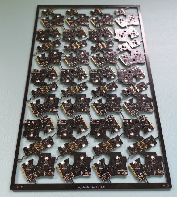
Unlike the UHK panels, the module panels contain numerous PCBs. The key cluster panel looks like some kind of modern art:
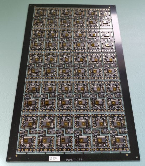
The trackball panel is very densely populated:
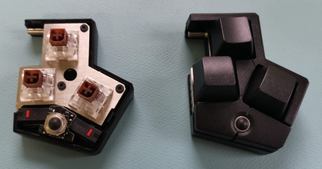
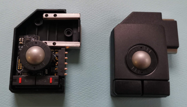
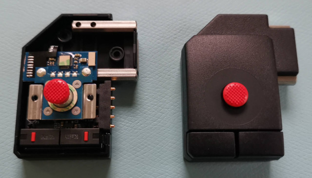
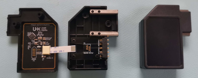
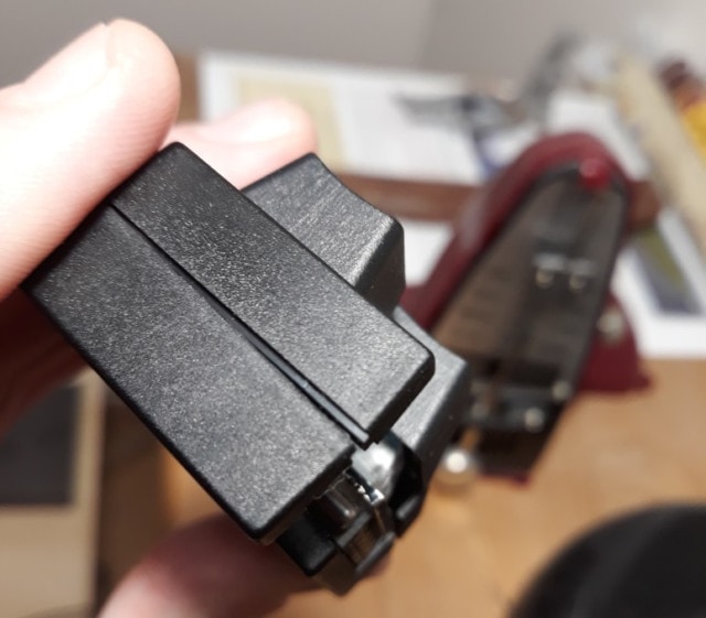
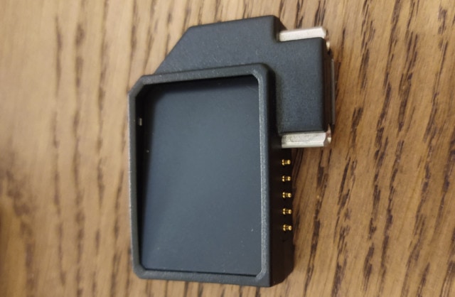
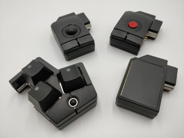
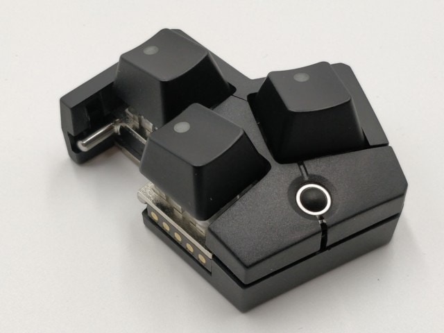
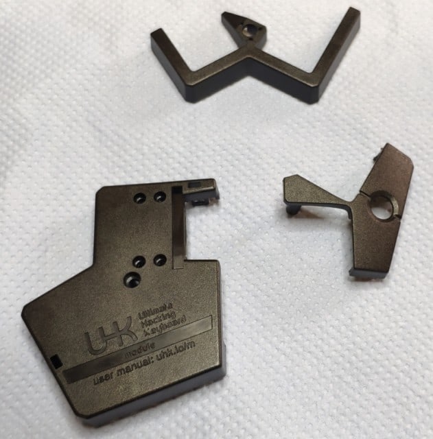
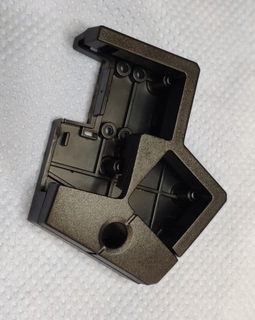
It’s interesting to peek into the modules, so here are some pictures of them half-assembled and fully assembled:
The following modules have been assembled so far:
The modules’ look and accuracy have greatly improved since I made the last module demo videos, so I’ve made some new ones. At the end of the videos, you can see the scrolling navigation mode in action assigned to the Mod layer of my UHK 60 v2. This mode makes it easy to zoom through a massive amount of content quickly, and it’s great to skim through documents.
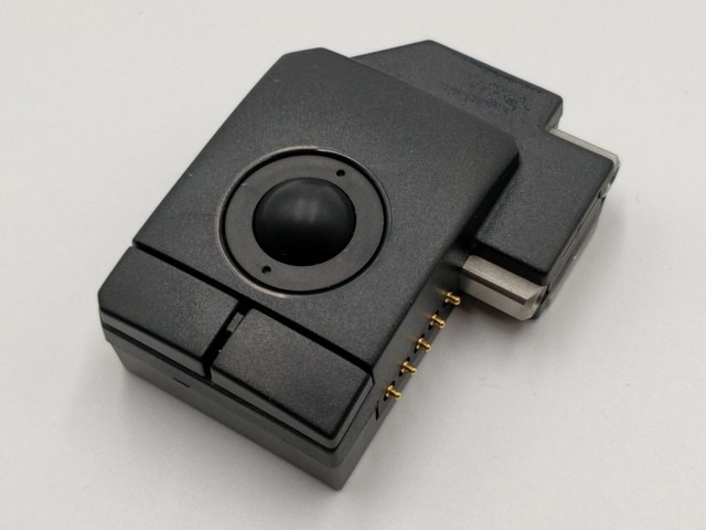
Let’s start with the trackball module.
We’ve tried many different balls, and we’re unsure whether to provide a light black resin ball or a heavier steel ball, so we’ll include both. We may eventually offer only one of these balls based on your feedback. The balls can be quickly replaced without tools, according to the following video.
The new, modified, injection-molded spacer improved trackpoint accuracy, and now it feels more accurate.
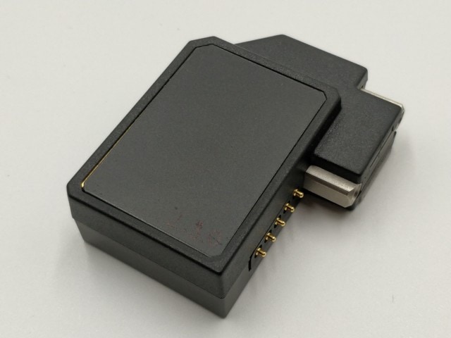
Beyond single tapping, the touchpad module supports two-finger tapping, two-finger scrolling, and pinch to zoom, but only tapping is supported at this point. We’ll add firmware support for every one of these actions soon.
Can the modules replace the mouse? It’s a question asked by many, so it’s worth an answer. The modules are a good fit to replace the mouse for regular desktop use, such as web browsing or interacting with applications. If you’re a graphics designer and spend a lot of time in Gimp or Photoshop, a mouse or a graphic tablet is a better choice, though. As for gaming, I think the modules are useful for specific games such as turn-based strategy, but I wouldn’t play fast-paced games, such as first-person shooters with them.
We keep shipping on a first-come, first-served basis, but the first 400 modules will be sent only to non-Crowd Supply backers. The reason for this is that Crowd Supply could potentially cause a weeks-long delay in delivery, and it is vital to get quick user feedback at the start of module mass production.
After shipping the first 400 modules, we’ll fully adhere to our first-come, first-served shipping policy, and we’ll be continuously producing and shipping module pre-orders as quickly as we can. So far, module mass-production has been a smooth ride, but it’s just started, so we don’t have reliable metrics on how long it’ll take to assemble all modules. We’ll provide you an estimate in our next monthly update.
In the meantime, make sure to update your address if you have moved to another location since your order.
Agent progress
Agent has evolved quite a bit recently, and now it’s able to detect every module and configure the actions of module keys and buttons.
A seamless experience of a fully-fledged product is kind of magical, and I believe that the above demo exemplifies it well. You can take a look at Agent’s web demo, which now includes the modules, too. We’re working hard to make the modules not only work for you but amuse you.
UHK 60 v2 progress
Two issues are blocking UHK 60 v2 production: PBT keycaps and plastic parts.
We’ve received a new PBT keycap sample set for approval since the last monthly update. This sample is a definite improvement over the previous one, but some keycaps’ shine-thru performance, especially the convex keycaps’, should be better. Our supplier is doing their best to maximize shine-through performance and provide improved samples soon.
As for the plastic parts of the UHK 60 v2, they’re larger than the modules and can only be molded with a larger machine. We have a great supplier who proved themselves, but due to a sudden influx of foreign orders, they’re quite overwhelmed these days and can only mold UHK 60 v2 parts around the end of April.
Most of you are very patient regarding such delays and primarily concerned about the quality of the final product which we highly appreciate, and we resonate with your mindset. Others are less patient which is understandable. We have dozens of suppliers, and even if one of them introduces a delay, the whole project gets delayed. These delays are often unexpected, and they’re among the top reasons why shipping hardware is so much harder than shipping software. We’ll do our best to push forward. We’re making sure that the wait worths it, and we’ll be keeping you updated.
Your tweets
You guys keep sending your awesome tweets, and we're always eager to read and feature them! If you got your modules, please share your love!
We’ll be keeping you updated on all things UHK and are looking forward to talking to you in mid-April. There’s a lot to do nowadays, so the update may be a bit late, but I’ll do my best.
Hi there, and welcome to this monthly UHK status update!
TL; DR: We’ve shipped a couple of modules to select testers, and their feedback was very positive, but they’ve also noticed some small issues. PBT keycap and ABS tooling are late, which affects estimated delivery dates. We plan to start shipping the modules around the end of February or March and the UHK 60 v2 around late March.
Module progress
Shortly before Christmas, we finished assembling the following modules and shipped them to select testers.
The feedback we received was very positive but also revealed some new issues. For some testers, the top and bottom parts of the key cluster came apart.
As for the touchpad, some testers pushed the top board into the module case.
Regarding the trackball, we’ve learned during the assembly process that the sealing ring slightly interfered with the ball in some cases, causing the ball to get stuck somewhat. We’ve also noticed that adding a slight pattern to the ball significantly improves optical sensor tracking at high speeds.
We haven’t heard any critiques of the trackpoint, which is unexpected because the spacer that held the top trackpoint part was 3D printed and slightly wiggled. We already had an injection-molded spacer, but we improved it, resulting in lower trackpoint operating force, and the mold hasn’t been modified yet, hence the 3D-printed part. If the 3D printed part was good enough, then the final molded part will be great.
We’re also removing a small plastic part that connects the two case buttons of right-handed modules based on tester feedback. This way, the buttons will be easier to press along their entire surface. The small plastic part was needed for the 3D-printed button prototypes to be sufficiently rigid, but injection-molded plastic behaves much better, and we’re better off without this part.
Luckily, all of the above issues are easy to fix by tweaking the molds, and our contractor is working on the fixes.
It’s fair to say that we’ve learned a ton from the testers’ feedback and the module assembly. I think we’re at a point where apart from the above fixes, the module hardware is excellent and cannot be improved significantly.
Our mold making contractor expects to update the module molds by the middle of February, and UHK 60 v2 mold modifications are expected to get ready by the beginning of March.
Keycap progress
Our PBT keycap supplier has finally sent us samples for approval. The majority of the keycaps’ shine-through performance is excellent, except for a handful of keys, including Space and Mod.
Several UHK 60 v1 owners wanted consistent key cluster keycaps, and as a result, we will also provide ABS keycaps for the key cluster. Our ABS keycap supplier is ready with convex 1U keycap molds, and we’ll ship every key cluster with both PBT and ABS keycaps. We expect to discontinue ABS keycaps for the key cluster in the far future, but now they’re included for free.
Our PBT keycap supplier recently told us that they can only provide the keycap sets in late March, which surprised us quite a bit. Previously, we only used ABS keycaps, which weren’t subjected to such delays.
As it turns out, manufacturing high quality, custom PBT keycaps of excellent shine-through performance is much more time consuming and complicated than making laser-engraved ABS keycaps, hence the delay.
We’re pushing our supplier to provide at least the key cluster PBT keycaps in March, enabling us to start shipping the modules sooner. Unfortunately, the UHK 60 v2 PBT keycaps will have to wait until the end of March despite our best effort.
Module configuration options
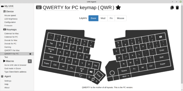
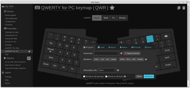
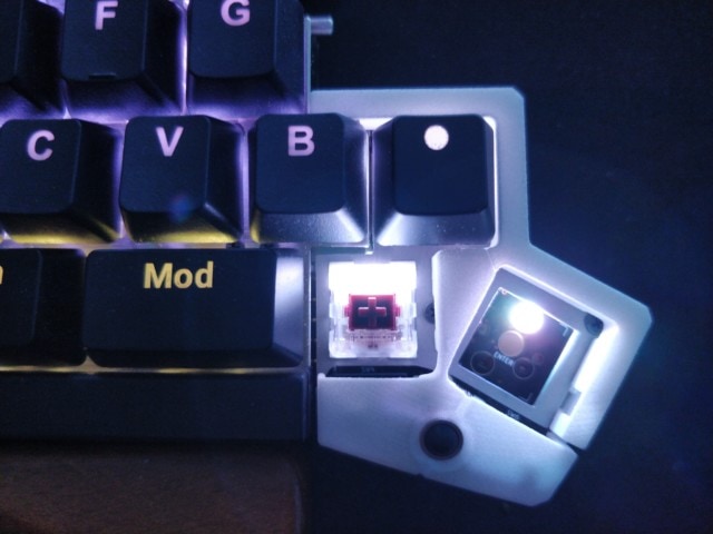
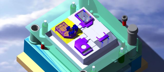
Agent’s master branch can already visualize the modules in real-time, and remapping them should be possible soon. The following screenshot is a work-in-progress, but you get the idea.
Remapping the modules, however, is not sufficient to make them live up to their full potential.
It can be difficult to hit small targets or take too much effort to make large motions with the pointer when using the modules. That’s where speed and acceleration settings come in. The speed setting is a linear multiplier, and the acceleration setting is an exponential multiplier. We’ve been already playing around with these values, and they make a world of difference.
When it comes to module usability, another critical feature is navigation mode, which determines what modules do when using their mousing instrument:
Cursor mode: moves the mouse cursor
Scroll mode: behaves like a scroll wheel
Caret mode: moves the text cursor, just like with up/down/left/right arrow keys
Media mode: invokes volume up, volume down, previous track, and next track on upward, downward, leftward, and rightward motions, respectively
Speed, acceleration, and navigation mode will be adjustable on a per-layer and per-module basis. So, for example, you’ll be able to make the trackball scroll when the mod layer is active.
By default, the navigation mode of the base, mouse, mod, and fn layers will be set to cursor, scroll, caret, and media mode, respectively, which are sensible and intuitive defaults given these layers’ default behavior.
I can think of a couple more minor options, and I’m sure the community will make further suggestions, but by and large, I’m quite confident that the above configuration options will provide sufficient freedom to achieve excellent usability.
Your tweets
You guys keep sending your awesome tweets, and we're always eager to read and feature them! I’m blown away by Sebastian’s review, Hubert’s chair mount hack, Alex’s custom tenting stand, and all the modded UHKs. Keep it up!
Hi there, and welcome to this delayed monthly UHK status update!
TL; DR: Except for small refinements, the molds of the modules are done, and we have some great looking samples to show you. We’ll send a couple of module prototypes to select testers in December. We plan to start module shipment at the end of January 2021. PBT keycap tooling is coming along nicely. Agent now has a dark mode.
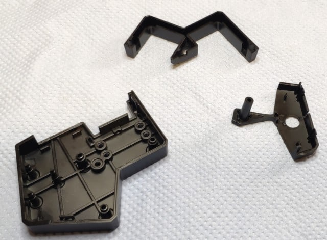
The modules look almost perfect from the outside. Minor surface defects result from not using the final injection molding machine and not setting optimal production parameters, both non-issues for the final production run.
Despite their nearly perfect look, some tooling changes still have to be done to the modules. We’ll fine-tune the length of the bosses of the microswitches to achieve optimal actuation force, and some other internal tweaks have to be done to optimize the parts for assembly.
The key cluster plastic parts should be fine as they are, and we don’t plan to make changes to them. The keycaps on the above photo are not final. The final keycaps will be made of PBT, and the bottom two keycaps will be convex.
Due to popular request, we’ll include three extra blank ABS keycaps for every key cluster for no additional cost to make key clusters more consistent with UHK 60 v1 keyboards.
The inner trackball housing needs to be adjusted for the distance between the ball and the optical sensor.
The trackpoint is already working fine, but we’re experimenting with optimal trackpoint cap height, which may affect the inner holder part. We plan to add a nice texture to the big glossy area near the cap. These are minor tooling changes.
The touchpad plastic parts work flawlessly. The golden edge at the left side won’t be visible as the final mylar sheet’s size will be corrected. The marker text which contains the version number of the PCB won’t be featured on the final product.
The above module plastic samples are surprisingly good for a first run. We aim for a second run in December, at which point the samples should be nearly perfect, and we plan to do a third run in January when we expect the samples to be flawless, and we plan to start shipping at the end of January 2021.
Plastic tooling does take more time than anticipated. We’re doing our best to release the modules as soon as we can. We won’t make any quality compromises, however, and the ETA will be extended if needed. We appreciate your continued patience, and we’ll be keeping you updated.
PBT keycap progress
As for the UHK 60 v2, our supplier sent us a photo of production PBT keycap samples.
Almost all custom legends look fine, but Mod, Space, and right Shift will be revised.
Join the dark side
Mad props go to our fabulous contributor, Mikko Lakomaa, as he has almost single-handedly implemented Agent’s dark mode.
Decided to nerd it up and recap my @UltHackKeyboard ... love the feel of these spherical keys and it looks beautiful to me as well. Was able to replace nonstandard keys in 3 places with blanks… the only issue is the BS key which is an R2 and thus a bit recessed. pic.twitter.com/7zmKnJDseh
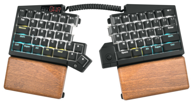
Hot-swap sockets, per-key RGB backlighting, double shot PBT keycaps, USB-C, braided cables, and much more - Say hi to the UHK 60 v2!
The previous UHK version, the UHK 60 v1, is out of stock and discontinued. The UHK 60 v2 is expected to ship around the end of January 2021, and you can pre-order yours now. We haven’t raised the price yet, but we will eventually. If you own a UHK 60 v1 and want to purchase accessories, be sure to read the “UHK 60 v1 parts availability and compatibility” section at the end of this update.
Regarding the modules, we’ve upgraded every key cluster module pre-order for free to per-key RGB backlighting, hot-swap sockets, and double-shot PBT keycaps. All the modules are fully compatible with both the UHK 60 v1 and the UHK 60 v2, and firmware upgrades will be released as usual. We expect the first injection molded parts of every module type to be ready in a week, at which point we’ll publish a dedicated update about them. In the meantime, please read the “Hot-swappable, backlit key cluster module” and “UHK 60 v2 timing rationale” sections below.
A little history
Our first keyboard, which you know as the Ultimate Hacking Keyboard, or more precisely as the UHK 60 v1, has been exceptionally well received. But it's been three years since we started mass production, and based on your feedback, we could make it even more powerful.
That is why we've been working over the last few years to take the UHK to the next level, keeping all you loved and adding everything you yearned for. The result is the UHK 60 v2, and we're super excited to unveil it now. If you liked the v1, you will love the v2.
I'll list all the improvements we've made, so you'll know if it's time for you to upgrade or purchase your first UHK. Fasten your seatbelts for this long ride.
Hot-swap sockets
Hot-swap sockets have been becoming increasingly popular in recent years. It's no surprise because they enable switch swapping, which makes replacing faulty switches or installing alternative switches a breeze.
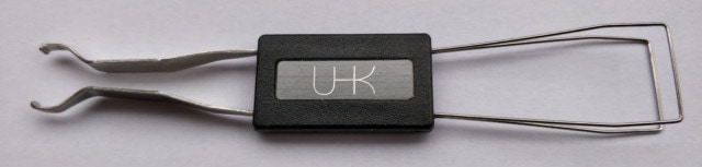
Speaking of replacing the switches of your UHK, we include a combined keycap and switch puller with every UHK 60 v2.
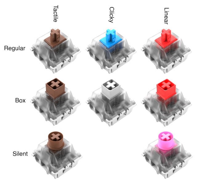
Regular, box, and silent switches
We can no longer offer the same switch types for the UHK 60 v2 that we provided for the UHK 60 v1 because they're not backlit-compatible. We also wanted to expand our switch range to offer a wider selection of quality product options. See the following switch matrix.
Let us first look at the vertical axis of the matrix. You're already familiar with regular MX switches, as their non-backlit version was available for the UHK 60 v1 and countless other keyboards. As for the box switches, they're my personal favorite. They feel more precise; they're better protected from dust and, in my opinion, offer a better typing experience. Last but not least, the silent switches make your UHK more bearable in noise-sensitive environments at the expense of some mushiness.
As for the matrix’s horizontal axis, I think clicky switches are the best typing choice, but your environment may not tolerate their noise. Gamers often prefer linear switches, and tactile switches are the best middle ground between typing and gaming.
The above switches are all made by Kailh. Currently, we offer every UHK switch option for the same price, but this will likely change eventually because some switches are considerably more expensive than others, especially the silent ones.
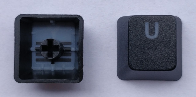
Double shot PBT keycaps
We have provided laser-etched ABS keycaps for the UHK 60 v1. Most were happy with them, but some pushed for PBT keycaps, and understandably so, as unlike ABS, the surface of PBT keycaps never gets shiny with use, and their legends never fade.
The parallel lines you can see on the above photo are the signature sign of double-shot keycaps. It's worth mentioning that these keycaps are best-in-class double shot PBT keycaps which offer unmatched shine-through performance, and the custom legends are easy to read even when they're not backlit.
The keycaps' side legends are here to stay, but they will be silk printed this time because laser-etching on PBT would have been very dark.
New keycap options
We've changed the keycap printing options for the UHK 60 v2. For the UHK 60 v1, you could choose Linux, Mac, Windows, Blank option, and ANSI vs. ISO was available as a separate option, resulting in 4 x 2 = 8 possibilities.
For the UHK 60 v2, you can select English US (ANSI), English UK (ISO), Blank ANSI, or Blank ISO. Being a backlit keyboard, we implemented the blank option by placing small translucent dots on every keycap. All these keycap options are made of double-shot PBT.
Functional per-key RGB backlighting
RGB backlighting needs no introduction, as you’ve probably seen countless backlit keyboards. The way the UHK uses RGB, however, is unique.
When I was thinking about adding RGB backlighting to the UHK, I had mixed feelings. I’ve seen loads of keyboards that tried to stand out by being flashy and utilizing all kinds of fancy colorful animations. In the true spirit of the UHK, it’s a professional tool, not a Christmas tree ornament, I thought, so I implemented what I call “functional backlighting.”
Based on the actual keymap and layer in use, every key has a function, and the keys light up according to the color of their function. See the following video.
As you can see, regular alphanumeric keys are white, modifiers are light blue, layer switcher keys are yellow, shortcuts are dark blue, mouse actions are green, macros are purple, keymap switch actions are red, and unused keys don’t light up. This color scheme is useful for learning what the keys of your UHK do, and Agent will allow you to configure the colors.
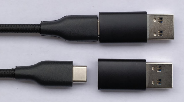
USB-C connector, adapter, and cables
USB-C needs no explanation as everything comes with it these days. What might not be so evident to some is that USB4 is on its way, and both ends of the USB cable will feature USB-C connectors. Naturally, we want the UHK 60 v2 to be as future-proof as possible while providing backward-compatibility.
As you can see, we offer a USB-C to USB-C cable with a USB-C to USB-A adapter, so you’re covered no matter what.
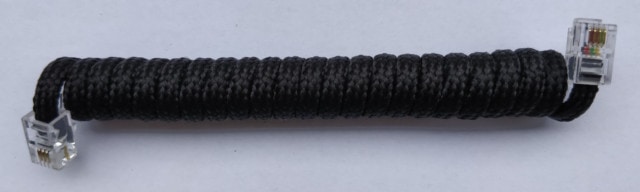
Unlike the USB cable of the UHK 60 v1, the new USB cable doesn’t have a ferrite choke at its end near the UHK, so it’s slimmer and also braided. For the sake of consistency, we’ve also braided the bridge cable.
We’ve made several improvements to USB connectivity besides simply switching to USB-C. The new USB connector is closer to the back side of the UHK, so it’s much easier to access it than the previous USB Mini-B connector, which sat deeper. And the redesigned cable recess mechanism should be more gentle with the cable and maximize its lifespan.
Hot-swappable feet
UHK 60 v1 feet were fixed by screws, and the legs had to be inserted into feet bases after screwing. This solution was reliable and worked well, but the feet’ installation and removal were quite time-consuming and demanding. This mechanism also discouraged experimentation with different setups, such as tenting versus negative-tilting.
The redesigned feet mounting mechanism makes all the difference as the legs are pre-assembled into the bases. You only have to gently insert the feet into the newly created recesses of the back of the UHK, then turn them clockwise. You can simply remove the feet by turning them counterclockwise.
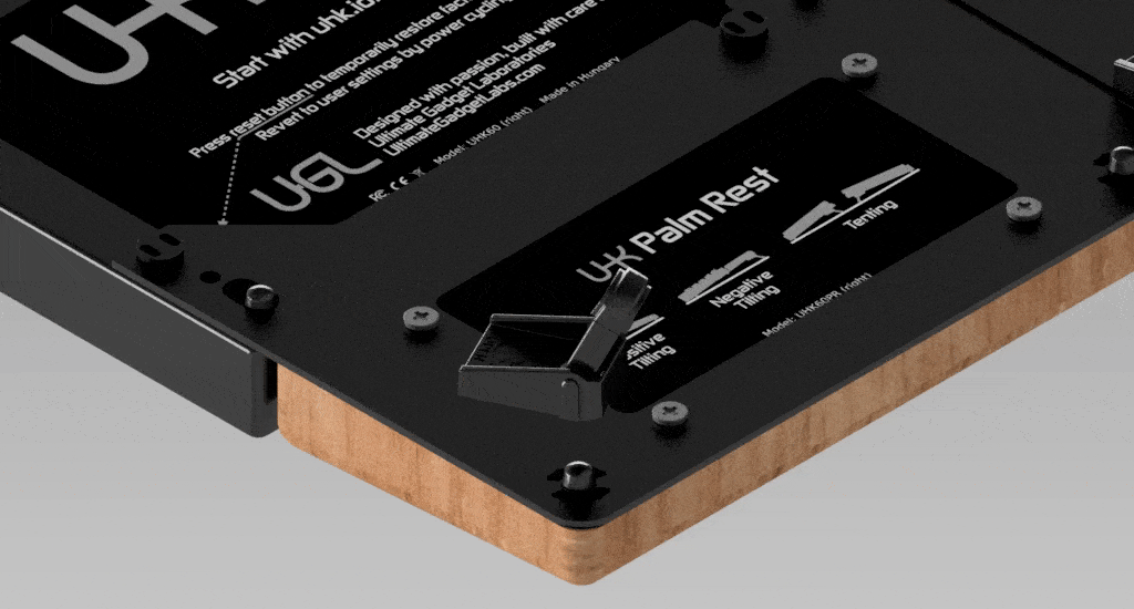
Removable palm rest
The palm rest had to be screwed to the UHK just like the feet. Screwing it was less of an inconvenience than screwing the feet, but it’s still useful to easily remove the palm rest for transportation, so now it’s possible.
You only have to screw a pair of plastic bolts per keyboard half into the existing bronze inserts of the UHK once. Then you can simply pull the palm rest apart from the UHK to unmount it and mount it in the opposite direction. If you want to use your UHK flat, the plastic bolts are not in the way.
Hot-swappable, backlit key cluster module
Although this is not a module update, it wouldn’t be complete without mentioning that the key cluster has also been upgraded to hot-swap sockets, per-key RGB backlighting, and double shot PBT keycaps. This free upgrade includes every key cluster pre-order ever made.
Regarding switch options, the switches of existing key cluster orders remain unchanged, but new key clusters are only available with the new switch types mentioned above going forward. Feel free to purchase alternative switches from any shop and replace them.
Production progress and ETA
The design and procurement of the UHK 60 v2 have been underway for years, and it’s very close to completion. We have already had the product FCC and CE certified, had the first batch of PCBs manufactured, ordered almost all parts, and the firmware is working with Agent.
The main thing that’s missing is the modification of the mold of the UHK case. The modifications will be barely visible from the outside except for the USB-C connector and the recess for the USB cable, but they still take some time. Our mold making contractor is busy with the module molds and expects to have the UHK 60 v2 mold ready by about the end of January 2021.
Another contractor is working on PBT keycap and keycap legend tooling, which are nearing completion and should be done well before case mold modifications.
UHK 60 v1 parts availability and compatibility
We’re committed to supporting UHK 60 v1 owners for as long as possible, so let me elaborate on parts availability and compatibility.
The v1 palm rest is discontinued, and you can only purchase the v2 palm rest going forward. We’ve only changed the palm rest’s base plate, which is only compatible with the new hot-swappable v2 feet. So if you’re a UHK 60 v1 owner looking for a palm rest, purchase the v2 palm rest and v2 feet. This way, your UHK 60 v1 uses v1 feet, and your v2 palm rest uses v2 feet. Similarly, if you already have a v1 palm rest, you can use it with the UHK 60 v2, in which case the v1 palm rest uses v1 feet, and the UHK 60 v2 uses v2 feet.
We have an extensive inventory of v1 feet and black v1 cases that will likely last for years to come. These items are incompatible with their v2 counterparts, and you can purchase them in the “UHK 60 v1 parts” section of our webshop.
The UHK 60 v1 keycap set is discontinued. Still, you can purchase the new UHK 60 v2 PBT keycap set for your UHK 60 v1 or wait a few weeks until we announce the availability of the UHK 60 v1 backlight upgrade kit in a dedicated newsletter.
UHK 60 v2 timing rationale
Some of you who are waiting for your pre-ordered modules may be frustrated that we started to develop the UHK 60 v2 before delivering the modules. This timing is because we wanted to take our technology stack to the next level as soon as possible. As a direct result, we were able to upgrade the key cluster module, which benefits everybody.
Alternatively, we’d have to release the key cluster module as originally envisioned without all these improvements, then release another version with the upgrades. We knew we’d implement these upgrades anyway, so we’ve taken a bigger leap forward.
Rest assured, the funds required to release the modules have already been allocated for them, so we’re not using the funds of module pre-orders to develop the UHK 60 v2.
Thank you for your patience as we move forward with production. We’re confident the chosen path results in a more capable product line.
Closing words
If you’re still here, then you’re one of the brave few, and we appreciate your interest. This update was probably the longest I’ve ever written, but there was a lot of ground to cover, and I wanted to leave no stone unturned.
The UHK 60 v2 is the culmination of all our experiences, and it’s been a huge effort to make it happen. It packs quite a punch, and it’s the best value we’ve ever provided, especially while we don’t raise its price. If you’ve been on the fence, it’s time to pull the trigger.
We’ll be keeping you updated about the UHK 60 v2 in our monthly updates, and I’ll publish an update about the modules in about a week.
Hi there, and welcome to the monthly status update of the UHK!
TL; DR: Machining of the right-side module molds is still underway, and it's taking longer than expected; hence, we’re now estimating that modules will begin shipping closer to the end of November In the meantime, we keep testing the modules, making small refinements, and improving their firmware.
Our contractor has been making further progress with the right-side module molds.
I spoke to our contractor yesterday. Unfortunately, the production of the molds is taking more time than originally anticipated, so we now expect to begin shipping the modules towards the end of November.
Understandably, production delays are always unwelcome. However, I know that the molds take so long because our contractor is doing his best in terms of quality. If you have been following us for a while, you know that the UHK was also delayed, and the reception was overwhelmingly positive. I’m firmly convinced that the modules will receive the same reception as the UHK with the care we give them.
We use the extra time available to us wisely and spend these days obsessing over the details of the modules. For example, we noticed that the mini trackball PCB of the key cluster module interfered a bit with the lower right keycap when pressed at certain angles, so we slightly modified the PCB. We also saw that the FPCs are very sensitive to sharp bends, so we redesigned the affected parts mechanically to minimize the bending.
The extra time allows me to polish the firmware and add more features. Recently, I implemented two-finger tapping and scrolling for the touchpad, and zooming is now also recognized. As for the trackball, I've just noticed that it's possible to double the resolution of the trackball sensor IC, which allows a higher sensitivity. These developments will improve the overall experience of the modules.
Speaking of the trackball, some of you have asked whether it's possible to clean the ball quickly. I'm happy to say that it only takes seconds to rotate the outer ring around the ball, which releases the ball.
As for the modules, some of you asked if the modules will remain firmly attached to the keyboard when it’s tented. The answer is a resounding “yes” because the precision-milled steel guides of the UHK keep very stable under all circumstances.
We’ll keep you informed about the development of the modules every month. They may take a while, but we work very hard to make them worth the wait.
Your tweets
You guys keep sending your awesome tweets, and we're always eager to read and feature them! If you got your UHK, please share your love!
Outer left wrist pain for months here, almost 100% cleared up from switching to the @UltHackKeyboard! I hoped it was going to have this much better effect and it certainly did.
#GotMyUHK about 2 weeks ago now and loving it. Has a lot of features I didn’t know I even needed. Bit of a learning curve in the beginning typing tented and split but not bad if you touch type. Excited to try out the modules when available. @UltHackKeyboard#MechanicalKeyboardpic.twitter.com/3bxuEzOUZ1
@UltHackKeyboard been using your keyboard for the last 6 months and it exceeds expectations in efficiency and ergonomics. Made some palm rests from purple hart (harder to make than I thought). Thanks for a great product. pic.twitter.com/6TLctIfmg3
Hi there, and welcome to the monthly UHK status update!
TL;DR: Machining of the right-side module molds is well underway, and we should have plastic parts by the end of August. We keep developing the UHK firmware and Agent, and it’s worth updating - not just because of module support.
Our contractor has been making solid progress with the right-side module molds.
If everything goes as planned, we’ll have injection-molded right-side module plastic pieces by the end of August, and we’ll start shipping the modules in September.
We’ve been publishing about one Agent and one firmware release per month over the past couple years. These releases contain numerous improvements, so feel free to check out recent Agent releases and recent firmware releases to see them along with their changelog. Also make sure to star these projects to get notifications about their activity on GitHub.
Regarding the firmware, it’s worth mentioning a recent fix which made the UHK play nicely with Ryzen PCs. Previously, in some cases, the UHK only worked via USB hubs when connected to Ryzen PCs. Strictly speaking, the UHK firmware was actually bug-free in this respect. The Ryzen platform just happens to be unreasonably picky regarding USB descriptors.
Speaking of Agent, a new feature makes key swapping extremely easy. You just have to drag a key to another key to swap them.
Now we’re working on making Agent handle the modules. Agent will display the actual state of the UHK just as previously demonstrated, but with the modules included. This will result in a very seamless and intuitive experience.
Your tweets
You guys keep sending your awesome tweets, and we're always eager to read and feature them! If you got your UHK, please share your love!
Palm rest attached and plugged in. Typing tweet with new keyboard. Wrist rest appears to solve my problems (of having to bend your wrists inwards to type on a normal keyboard). I hope I can get used to the split! Does anyone else use one? pic.twitter.com/Zo1HznJP61
Hi there, and welcome to the monthly UHK status update!
TL;DR: The molds of the key cluster module are ready. Machining of the right-side module molds is in progress. The design of the module plastic parts has taken more time than anticipated, and as a result, we expect to start shipping the modules in September.
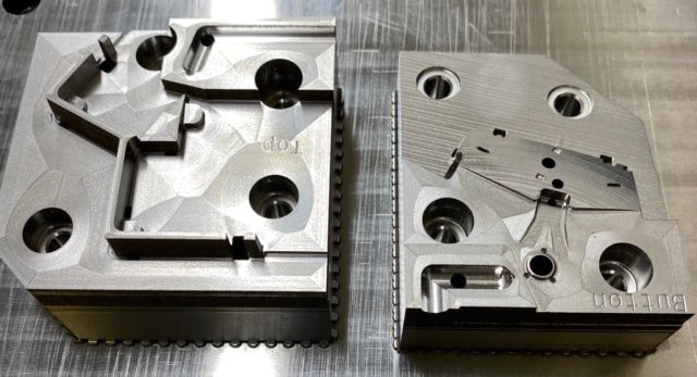
The key cluster molds are finally ready, and the molded plastic parts look great:
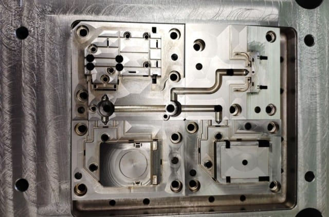
Now, our contractor is working on the right-side module molds:
The right-side module molds are expected to be ready around the end of August, and we plan to start shipping the modules in September.
We’ve been working on the modules as hard as we could, but despite our best effort, the ETA had to be updated because the design of the module plastic parts has taken more time than anticipated. We believe that the updated September ETA is realistic, and we’ll do our best to hit it.
Wildcat’s UHK review is a special one as he doesn’t say a single word, and yet, he tells much more than most reviewers. It’s an unusually enjoyable video which I highly recommend watching.
You guys keep sending your awesome tweets and posts, and we're always eager to read and feature them. If you got your UHK, please share your love!
not too long ago I started to feel pretty bad wrist strain and fatigue while typing so I made the call to get a Ultimate Hacking Keyboard and then kitted it out with a really pretty keycap set pic.twitter.com/9TdYE4TtVz
i’m pretty new to nerd keyboards, but i’m really digging the @UltHackKeyboard after a few weeks of breaking it in. using the mod layer (mapped to right space) to activate arrow keys with h/j/k/l and scroll with u/i has been game changing 🎹 pic.twitter.com/upAwMKgQQd
Hi there, and welcome to the monthly UHK status update!
TL;DR: The molds of the key cluster module are almost ready. The PCBs are finalized and being panelized. Module parts are pouring in from our suppliers.
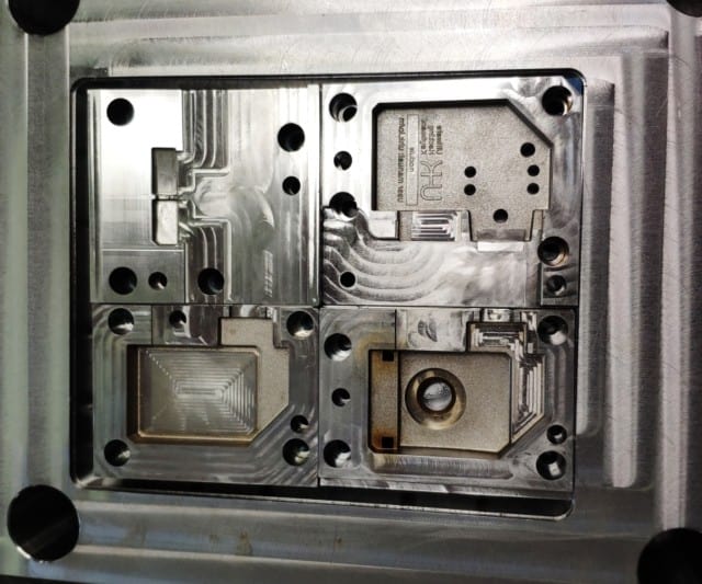
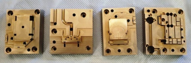
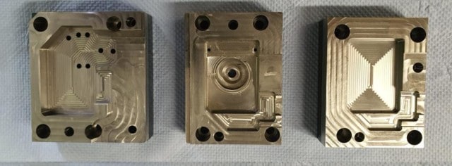
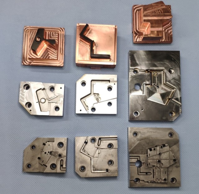
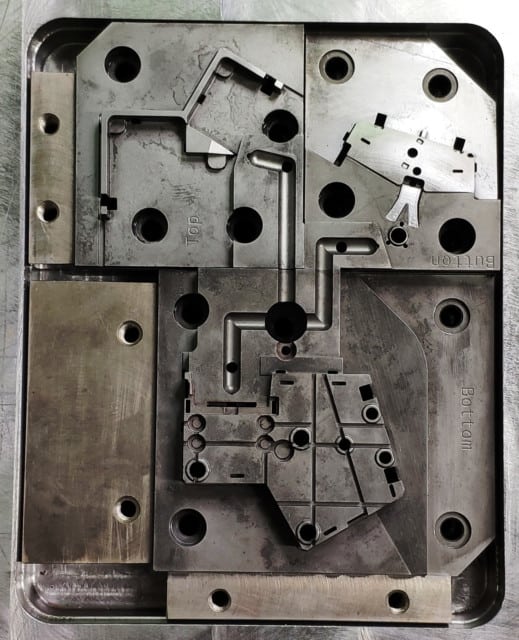
Our contractor is almost ready with the key cluster molds. This is how they look:
The testing of these molds is slated for the end of June, meaning that we’ll soon have key cluster plastic pieces to show you.
As for the right-side modules, András approved the design of the latest 3D-printed parts, and injection molding simulations have been made:
Even more importantly, our contractor started fabricating the right-side module molds:
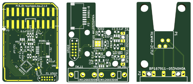
As for the module PCBs, I’ve been making some small improvements to them. Their shape and layout have been finalized, and I don’t expect any more changes, so we’re in the process of panelizing them.
I’m very pleased with the overall design of the modules, as they do their job well, they are as simple as possible, and they’re highly optimized for production. In my book, this is good design.
Parts have been pouring in from our suppliers, and most have arrived - including the mini trackballs of the key cluster, the balls, optical sensors, and lenses of the trackball module, FPC cables, and FFCs (flexible printed circuits).
You guys keep sending your awesome tweets, and we're always eager to read and feature them! If you got your UHK, please share your love!
Since I #GotMyUHK last year, I am amazed by its productivity (open firmware + macro language by https://t.co/7mIDhgt5Qv) its ergonomics (two halves) and its customizability. Here you see it in action in one of my Machine Learning for Physicists lectures from last semester. pic.twitter.com/LsYt3mNRHV
#GotMyUHK and really love it but it’s not really a hacking keyboard until you start hacking it.
Gateron black ink switches and GMK Keycaps make a huge difference and are totally worth it IMO, although not cheap. Can’t wait for the modules! pic.twitter.com/NyTyEFswH0
Hi there, and welcome to the monthly UHK status update!
TL;DR: The schematics and BOMs of the module PCBs and FPCs (Flexible Printed Circuits) have been finalized. Every part has been ordered for the modules.
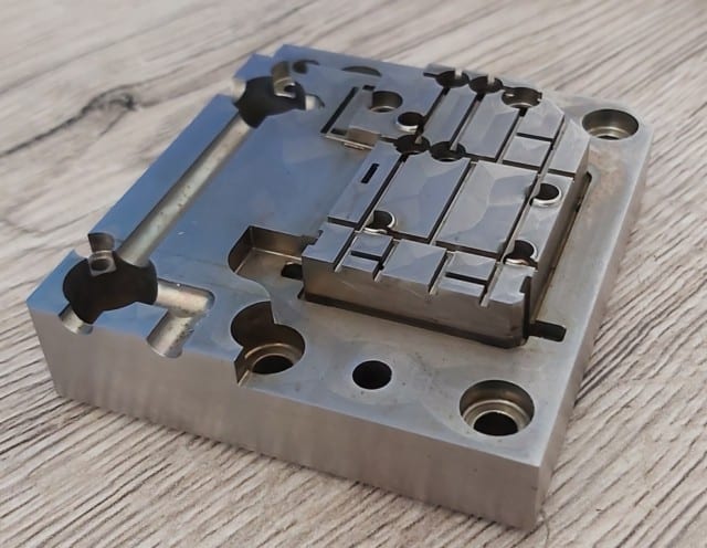
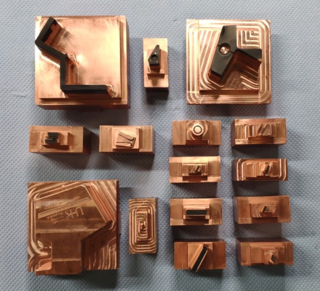
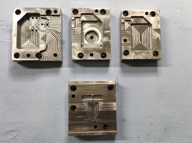
Our contractor keeps making progress with the key cluster mold. This is how it looks:
As for the right-side modules, András has been refining their mechanical design, and I’ve been tweaking their PCBs accordingly. These are some of the boards I’ve redesigned recently:
I consider the schematics and BOMs of each PCB and FPC to be fully finalized. András and I will meet over the next week and check how well the new 3D printed module cases fit with the new PCBs. Chances are high that everything will fit well, at which point the machining of the right-side module molds will begin.
I recently visited our EMC tester, TÜV, and we put the modules into the test chamber. The modules did not affect the measurements, which is exactly what I expected based on their small power consumption and small size. Given these results, the modules should pass the EMC tests with flying colors.
We’ve ordered every part of the modules from our suppliers. No parts shortages or delays are expected.
These days are unusually eventful due to the modules, hence this fabulously late monthly update. I’ll do my best to keep you up to date in a timely manner going forward, but I’ll keep prioritizing module development and production over the monthly updates for everyone’s sake.
Your tweets
You guys keep sending your awesome tweets, and we're always eager to read and feature them! If you got your UHK, please share your love!
VS Code on the iPad! Well, kind of. Technically it is running on the Raspberry Pi, powered and networked via USB-C. This setup would be pretty useful if Remote and/or Codespaces extensions worked. Unfortunately, both are closed-source and not available for ARM. Ask me anything! pic.twitter.com/gYdKgwYfuw
I had to get a bit creative with backspace, enter and \ to accommodate the unusual key widths on the right side, and had to keep the stock mod/space keys, but that should work out I hope. pic.twitter.com/figY6vET1K
Hi there, and welcome to the monthly UHK status update!
TL;DR: Key cluster mold manufacturing is well underway. We’re getting close to the final design of the right side module molds, too.
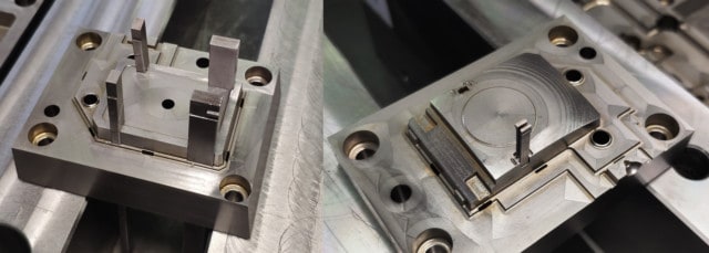
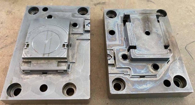
Since our last monthly update, the design of the key cluster molds has been finalized, and now they’re under production. It’s always quite an experience to witness hunks of steel taking shape.
In the meantime, András and our contractor have been working hard to finalize the design of the right-side modules. As soon as this design gets finalized, our contractor will start to get these molds machined.
We’ve also ordered various parts, such as the optical sensor of the trackball, the mini trackball of the key cluster, and the FFC cables. This is quite an intense process for everyone involved, and we’re doing our best to hit our July ETA.
New keyboard in the house! 🥰 #GotMyUHK a day earlier than I expected. Super solid build quality, feels wonderful under my fingertips! Now I just have to adapt to it and partially relearn how to type, but I think it'll be worth it. Already fallen in love with the mouse mode! pic.twitter.com/ahmC7ZOuRm
Where was mouse mode on a keyboard all my life? If you roam from room to room with a laptop trying to avoid the kids to get some work done @UltHackKeyboard is the only way to get anything done without getting a tendinitis in the process