Hi there, and welcome to our monthly status update!
TL;DR: The BOM is fully finalized and ordered. The UHK prototypes have improved a ton in the EMC department. Agent and the firmware has evolved a lot. The key cluster and trackball modules have been mechanically prototyped and tested. New developers joined our forces. We've tested the molds and found some issues which will introduce some delay. We plan to ship a pilot run of 50 UHKs in July. The rest of the UHKs are planned to be shipped starting from August. Please read on!
You can always check out the expected delivery date and update your shipping address on your Crowd Supply account page.
EMC improvements
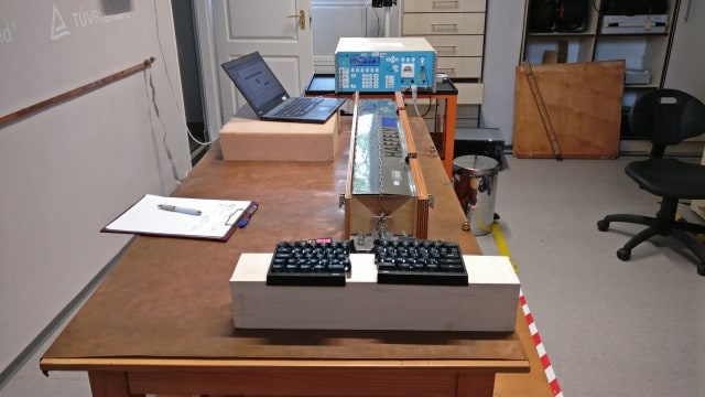
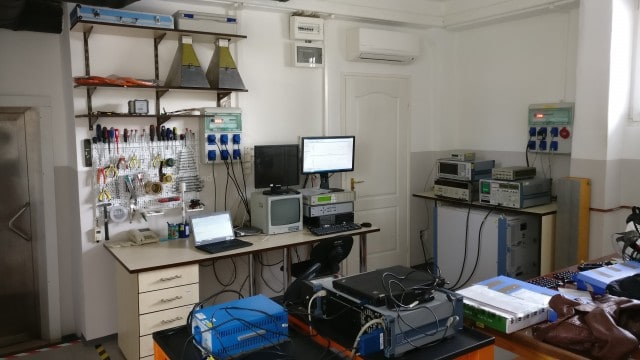
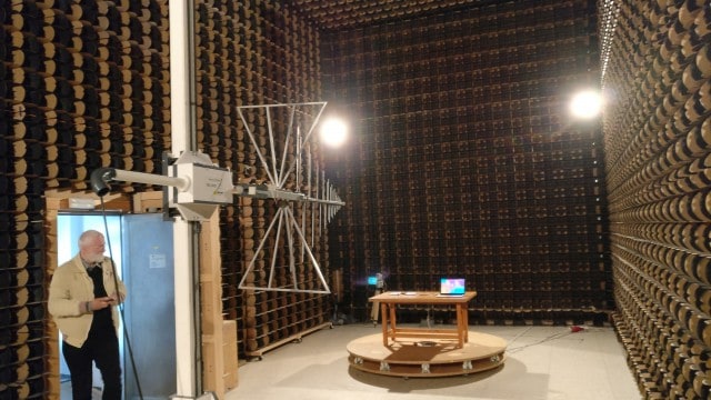
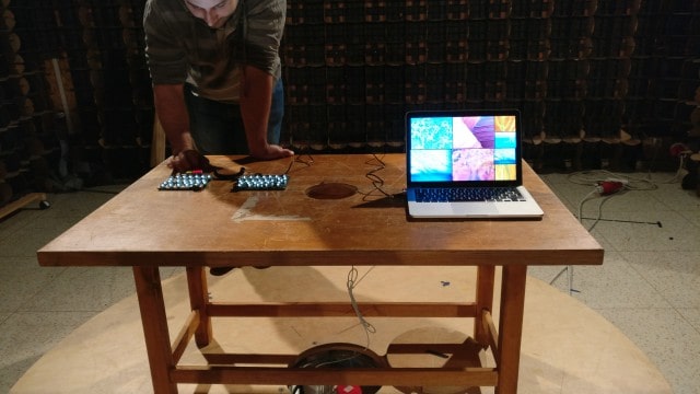
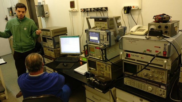
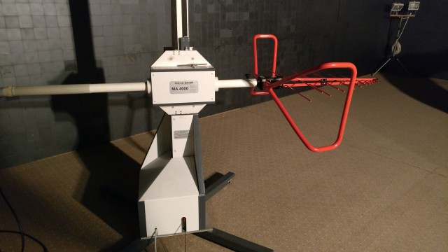
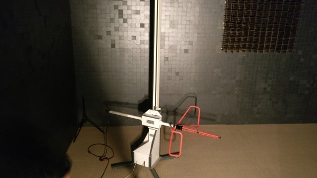
We've been visiting the EMC lab of TÜV since our first successful test. The reason is twofold. First, we wanted to improve on the results, and second, there were some further tests to be done.
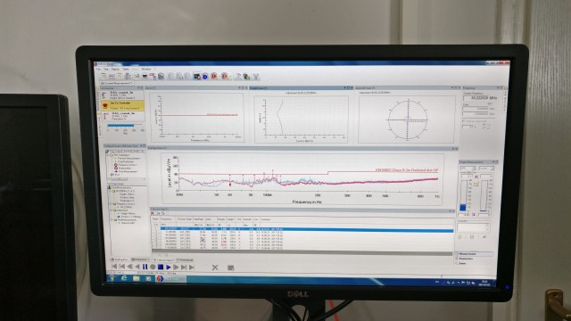
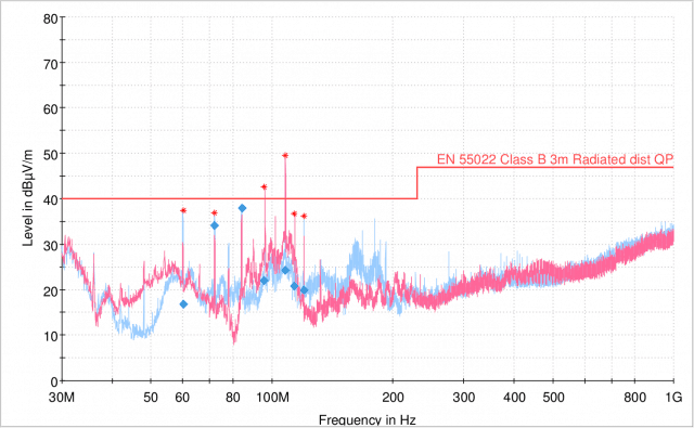
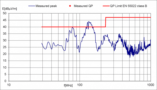
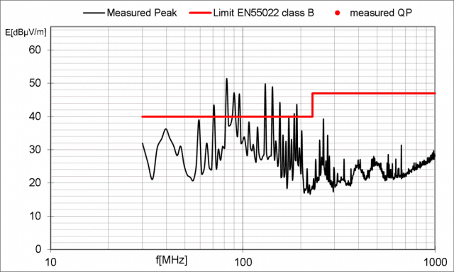
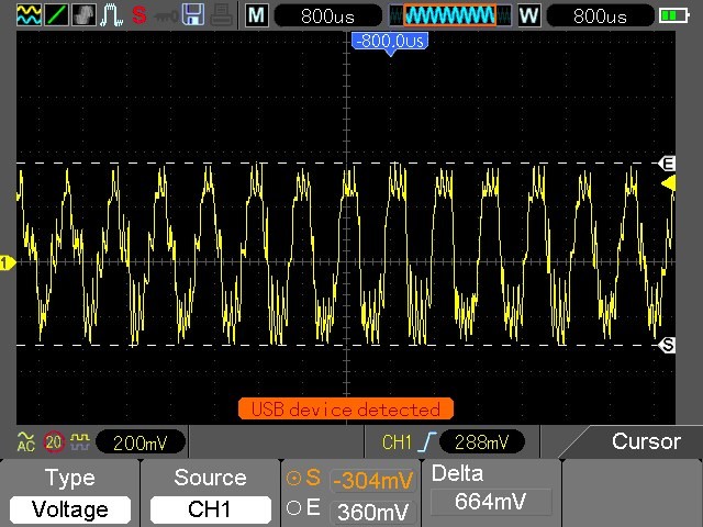
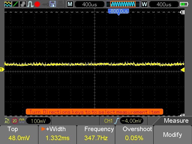
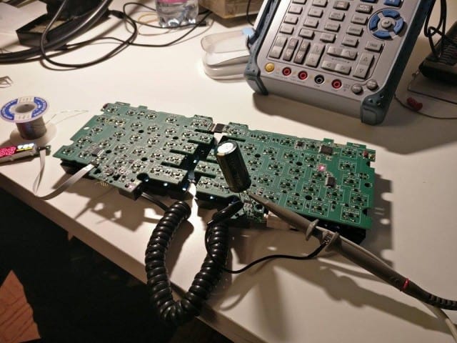
The testing results that we shared with you the last time already passed, but the safety margin was only 2 dbμV/m, instead of the recommended 5 dbμV/m. Our worry was that the margin was so thin that it was possible for the final test to fail. We really wanted to avoid any potential failure, so we have been tweaking various resistor and capacitor values, and have been trying various bridge cables and USB cables to make the margin wider.
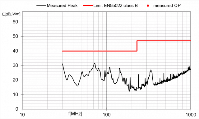
You know what made a drastic difference? The USB cable. As soon as we tried a USB cable with a ferrite choke on the keyboard end, the EMC graph changed very substantially. Don't worry, this ferrite choke is only 24 mm x 14 mm in size, and it's very light so it doesn't weigh down the cable.
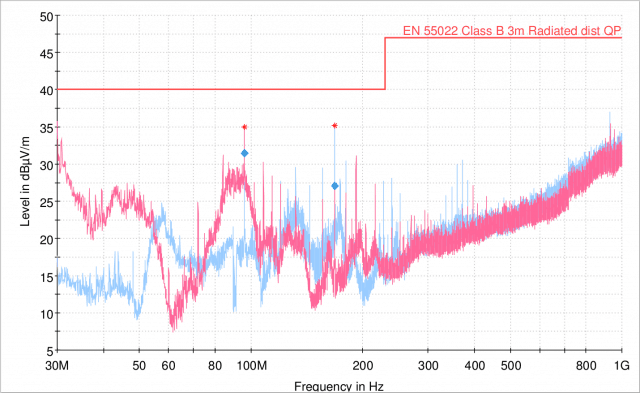
According to this graph, we went from a 2 dbμV/m safety margin to about 18 dbμV/m! (See the vertical distance between the blue mark around 100M and the red line.) Given these results, we'd be extremely surprised not to pass the final test.
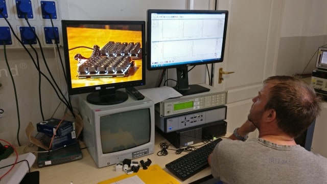
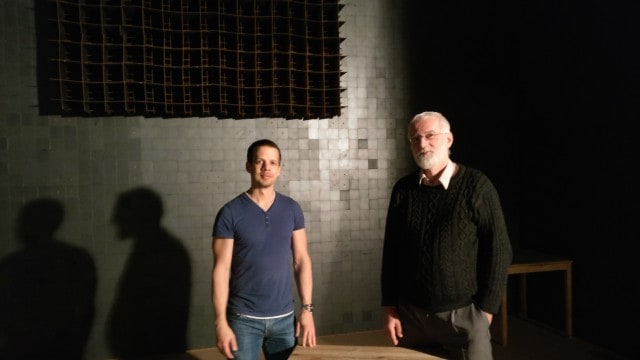
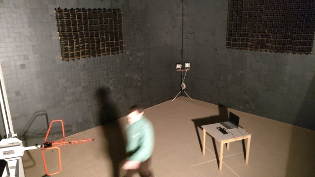
We've also conducted some further tests that we haven't done before. First, we put the prototype into the test chamber and tried to disturb it with focused radiation. We were watching it with a camera to see whether the LEDs go out, and checked it after the test. The prototype didn't break a sweat and kept functioning perfectly.
In the second test, the USB cable was put into a metal cage, and got a healthy dose of radiation. The criteria for this test is that the device can go out of service, but ultimately, it must recover by the end of the test.
The first time this test was executed, the LEDs on the left keyboard half went out and it didn't recover. After that, I made the firmware much more robust, and as a result, the left keyboard half was able to recover like a champ.
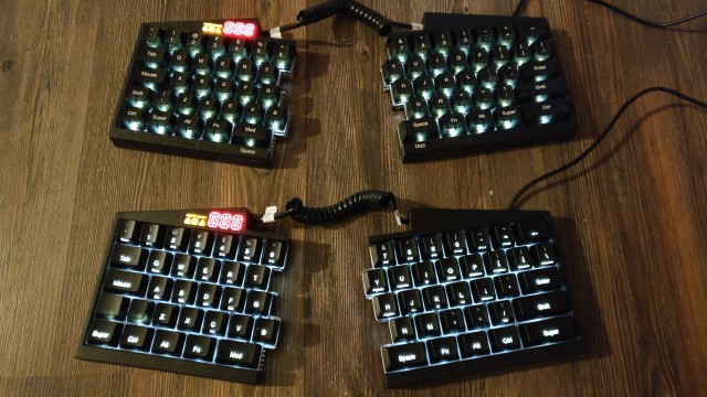
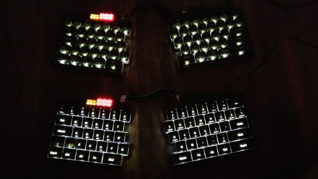
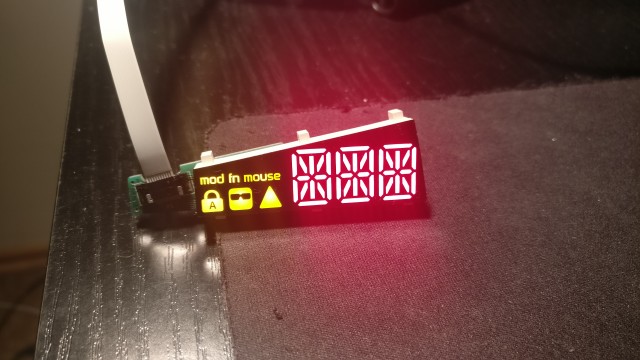
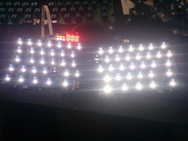
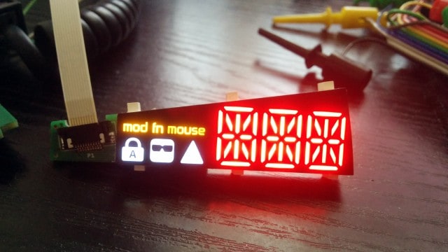
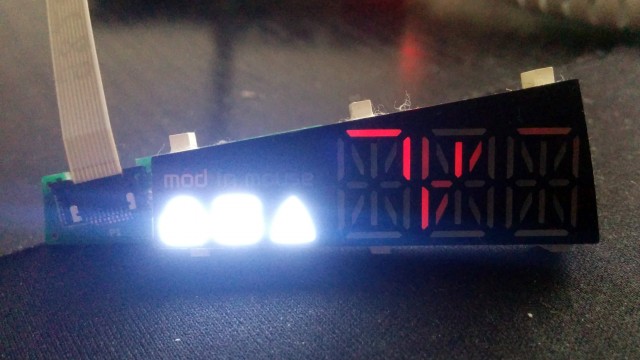
Speaking of LEDs, we got so many inquiries about backlighting that it justified its own post, so here you are: Everything about UHK backlighting.
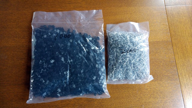
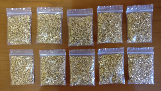
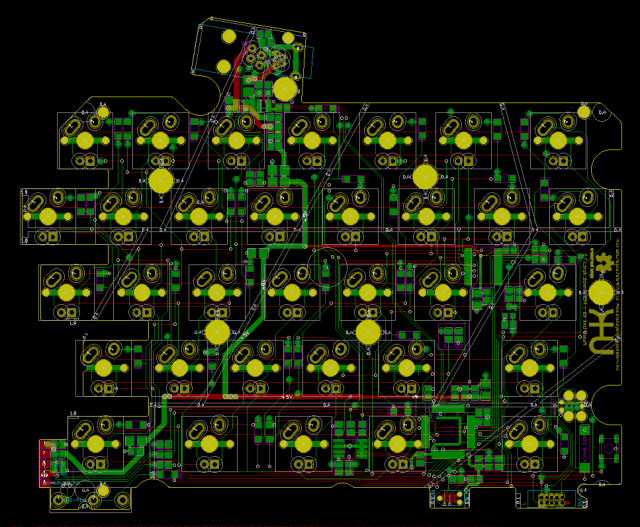
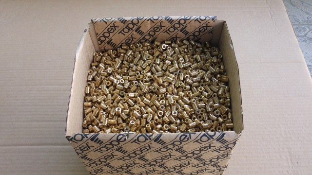
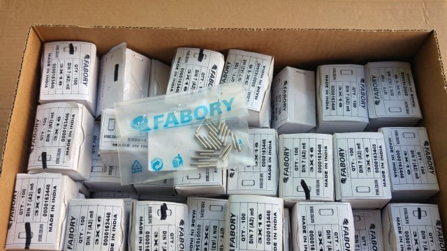
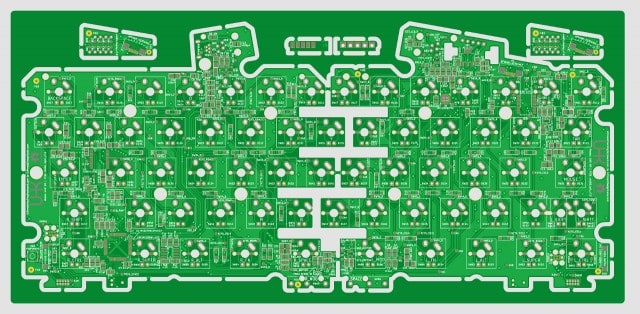
Things are looking so good in the EMC department that I fully finalized and ordered the BOM for the PCBs of 2,000 UHKs, and if everything goes well the UHK will be certified very soon, possibly in June.
Agent progress
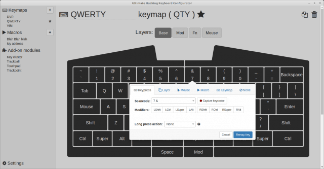
A lot has been happening to Agent, our configuration application recently. Józsi is still involved in the development of Agent, but he told me that going forward, he cannot guarantee a fixed number of working hours per month because his life got a lot busier. This made me search for the right candidates, and I'm happy to report that I found two excellent developers.
Róbert Kiss is busy with some of the most pressing Agent issues. Agent has an initial OS-specific privilege escalation step that allows it to access the USB interface of the UHK. Robi implemented the missing Windows-specific part of the privilege escalation step. He's also set up a build process, so that now Travis generates releases for Linux and Macintosh, and AppVeyor generates releases for Windows, and these files get uploaded to the releases section of GitHub. He's also mostly finished the auto-update mechanism of Agent.
Attila Csányi will be busy with a number of important but less time consuming issues given his limited time. He's already made the macro layout more responsive and made the currently selected key highlight and animate very nicely. These seemingly small issues add up big time when it comes to user experience.
Luckily, Józsi is still involved with the development of Agent. Lately, among other things, he's implemented ISO/ANSI layouts. Agent used to display only the ANSI layout but this change will allow it to show the correct layout, be it ISO or ANSI as soon as you plug in your UHK.
Firmware progress
Substantial progress has been made with the firmware recently. The easier part was making the communication between the halves more robust. First up, I added a CRC16-CCITT checksum to the messages between the keyboard halves to improve message integrity. Next up, I implemented a recovery mechanism for LED drivers so that the LEDs also recover when disconnecting/reconnecting the halves. I also made the communication packets between the halves more efficient and smaller.
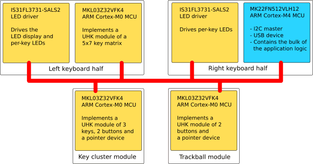
The harder part is upgrading the firmware of the left keyboard half and modules via USB. You see, it's fairly easy to upgrade the firmware of the right keyboard half because it's directly connected to the host computer. The modules and left keyboard half however are not directly connected via USB. They're connected via an I2C bus to the right keyboard half.
The plan is to implement a proxy mode for the right keyboard half, so that it can route the firmware from the USB host to the left keyboard half and to the modules via I2C. Luckily, such a protocol translator is already implemented so we can use it. It's called BusPal, and it's part of the KBOOT (Kinetis bootloader) package. Unfortunately, it's not nearly as mature as KBOOT, and it was obvious that integrating it to the UHK firmware won't be a walk in the park. I was searching for a proficient developer to make this happen but despite my best shot, I couldn't find a right candidate, so I had to try to integrate BusPal myself.
There were three variants of BusPal within the KBOOT package but I noticed that only one supported USB, so I picked it. In the beginning, I couldn't even build it because it was developed using the the proprietary IAR embedded workbench, not with the free Kinetis Development Studio that is based on Eclipse and GCC. I simply started by putting BusPal into a subdirectory of our firmware repo and trying to make it work. It was an uphill battle at first because BusPal has a huge codebase of which we need very little functionality. Just making the compiler happy has taken days, and after that it was even more work to make it functional. Luckily, over the course of about two weeks, BusPal enumerated over USB and could talk to the left keyboard half. Well, mostly.
Now, I can send protocol commands to the left keyboard half via BusPal but they don't work every time. As it turns out, the ROM bootloader of the KL03, the processor of the left keyboard half is buggy as documented by errata ID 8060, and these bugs have to be worked around. I can erase the processor and query properties, but the firmware upgrade command breaks. Given my myriad of responsibilities, I'd much rather delegate this last step, and it seems that I might have just found the ultimate developer. More about him later.
The state of modules
Up until this point, not too much has been said about the progress of the modules. That's because our primary focus is getting the UHK to market, so András only works on the modules when he has some free time.
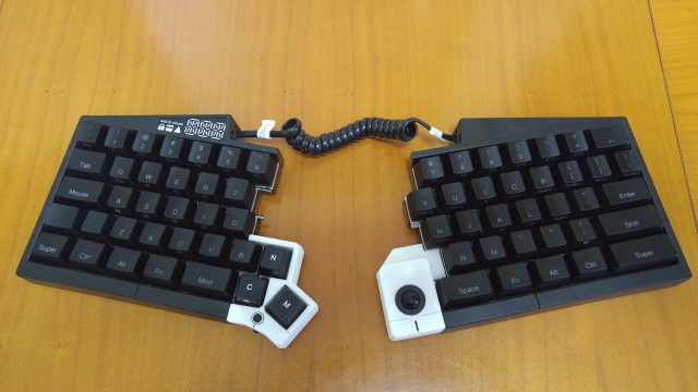
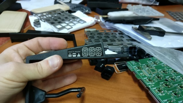
At last, I'm happy to show you the first version of the 3D printed modules:
These prototypes were printed using a white, powder-like material, but the final modules will be offered in black color.
Originally, we created two versions of the modules, one of them being totally flat, the other one being angled.
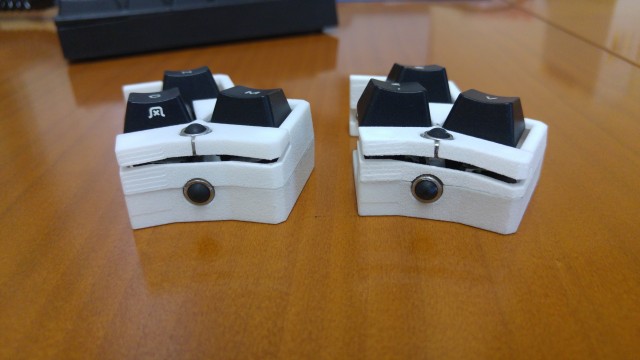
We've been experimenting with a front and a top mini trackball on the key cluster module, but concluded that the top one is much more usable, so we'll ditch the front-sided mini trackball.
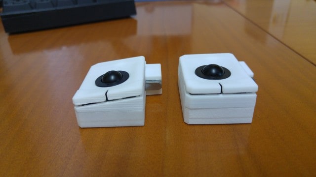
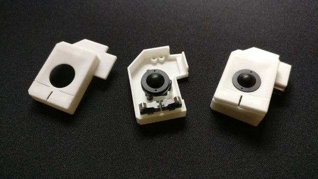
The reason we've made two versions is to test them and see which version is more ergonomic. The flat modules made our thumbs stretch significantly less, so we're confident that they're a better choice. This is also very fortunate from a manufacturing standpoint as the space inside of the modules is very limited, and even more so in their angled versions, so the flat versions will be easier to design and manufacture.
We also found that it's not a good idea to use two buttons per module because the inner button which is closer to the UHK usually gets pressed when pressing the case button of the UHK. Our plan is to only feature a single button per module, the outer button that is farther from the case button of the UHK.
This is a big step forward, but there's still a lot to do in the future. These plastic cases don't contain PCBs yet, so they will have to be designed. Luckily, the left keyboard half is an module from an electrical, firmware, and protocol standpoint, so we will be able to reuse its schematic and firmware. These plastic cases of the modules are only made for mechanical testing purposes and need to be redesigned here and there because they are not manufacturable, and lack structural support.
Molding plastic parts
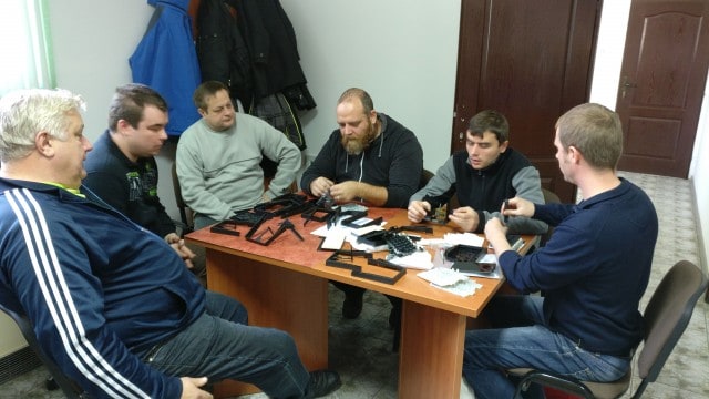
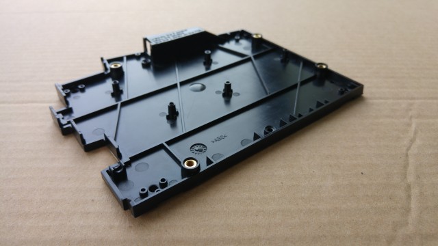
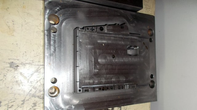
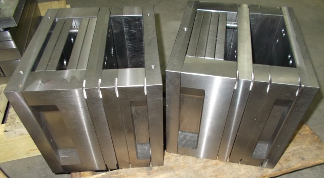
I'm a software developer by trade, so I have little knowledge about injection molding. A couple days earlier however, I was fortunate enough to observe the process up close in an injection molding facility where we tested our molds.
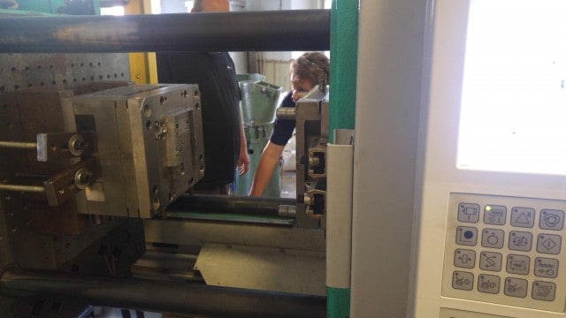
As so many things, injection molding looks deceptively simple. Plastic flows into a mold, and the perfect plastic part falls out of the machine. Just like on this video:
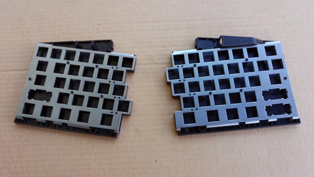
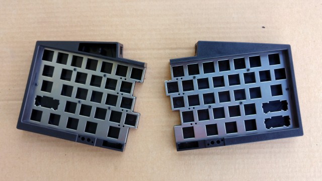
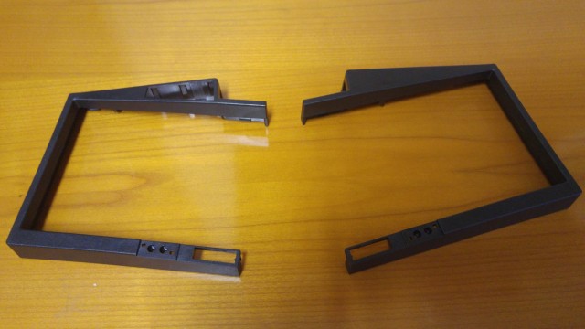
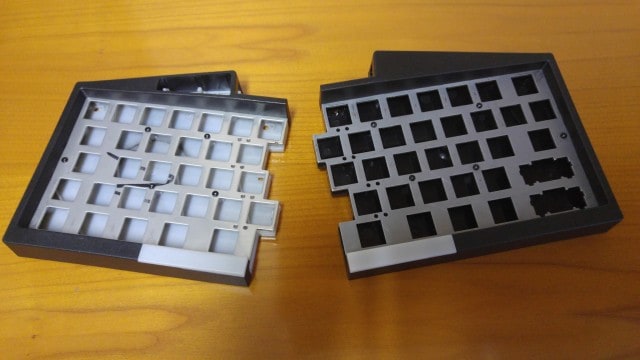
In practice, lot of things can make a plastic part less than perfect, such as warping, which is the major issue we have mostly fixed.
You see, warping is a very common phenomenon, and it's usually so slight it doesn't matter. In our case however, it does. As it turns out, of all the keyboards ever created, the UHK is probably the most sensitive to warping. This is because when the plastic cases of the two keyboard halves are merged, it becomes extremely pronounced.
When the UHK is merged and the halves warp even slightly, a very slight V shape can be noticed. This shape raises the four outer legs while the four inner legs firmly touch the ground which is obviously unacceptable.
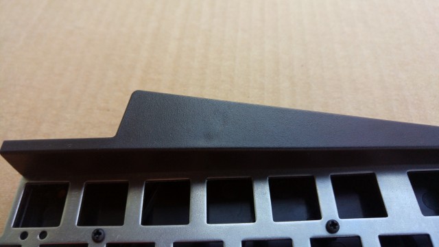
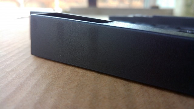
Surface finish issues, such as sink marks and surface defects are another category of injection molding issues we have to deal with which we have also mostly fixed.
One way to fix the above issues is to tweak various mold and injection parameters which we were actively pursuing quite successfully during our three-day stay at the factory. It's mind-boggling how many parameters can be tweaked, such as the injection speed, pressure, after-pressure, mold temperature, the duration of the molding process, and many more. To make things even more complicated, these parameters are not single numeric values but rather graphs, and multiple points of the graph can be set along the time axis!
The other way to fix these issues is to modify the molds themselves. This is usually more time consuming and involves machining the molds in various ways. Some of our issues can only be solved this way.
We have a rough schedule in place regarding the plastic parts:
- Within days, the injection-molded cases will be scanned with a 3D laser scanner to reveal the inaccuracies for the molds to be fixed.
- In the next week, the left and right bottom molds will be fixed according to the above results.
- Another week later, we'll mass-produce the bottom parts for the pilot run.
- Within a month, we'll get all the molds fixed, fine-tune technological parameters, and manufacture every plastic part for the pilot run.
As for the big picture schedule:
- In July, we’ll manufacture a pilot run of 50 UHKs and send them out to our pilot testers, which include the various developers, contributors, and backers who have helped us along the way and indicated a willingness to help us rigorously test the UHKs before the main production run and work out any final kinks should they arise. All 50 pilot run units have been assigned, but if any of our pilot testers drops out and we need to fill a spot, we'll solicit volunteers. We haven’t talked about the pilot run yet, but we think it’s critical for the first UHKs to be tested before we actually start the main production run.
- In August, we'll launch the mass production of the remaining 1,950 UHKs. The goods will flow out continuously and be shipped approximately in the order they were purchased. Since we are using fulfillment centers in both Hungary and the US, there will be some variation in when your order is shipped, depending on your shipping address, but, basically, the sooner you ordered your UHK, the sooner you'll receive it.
Thank you for reading this update! As you can see, we have to deal with the molding issues which do introduce some delay, but at the same time, we're also making rapid progress. We're asking for your patience and support during these last miles. We'll make sure the UHK will be worth the wait.
As always, we'll be keeping you updated on a weekly basis on social media, and on a monthly basis in this blog and our newsletter.
Talk to you on 2017-07-13!
