Important: Please make sure that your shipping address is up to date! You can change it on your Crowd Supply account page. Please also check out the delivery status page.
Hi there, and welcome to our monthly status update!
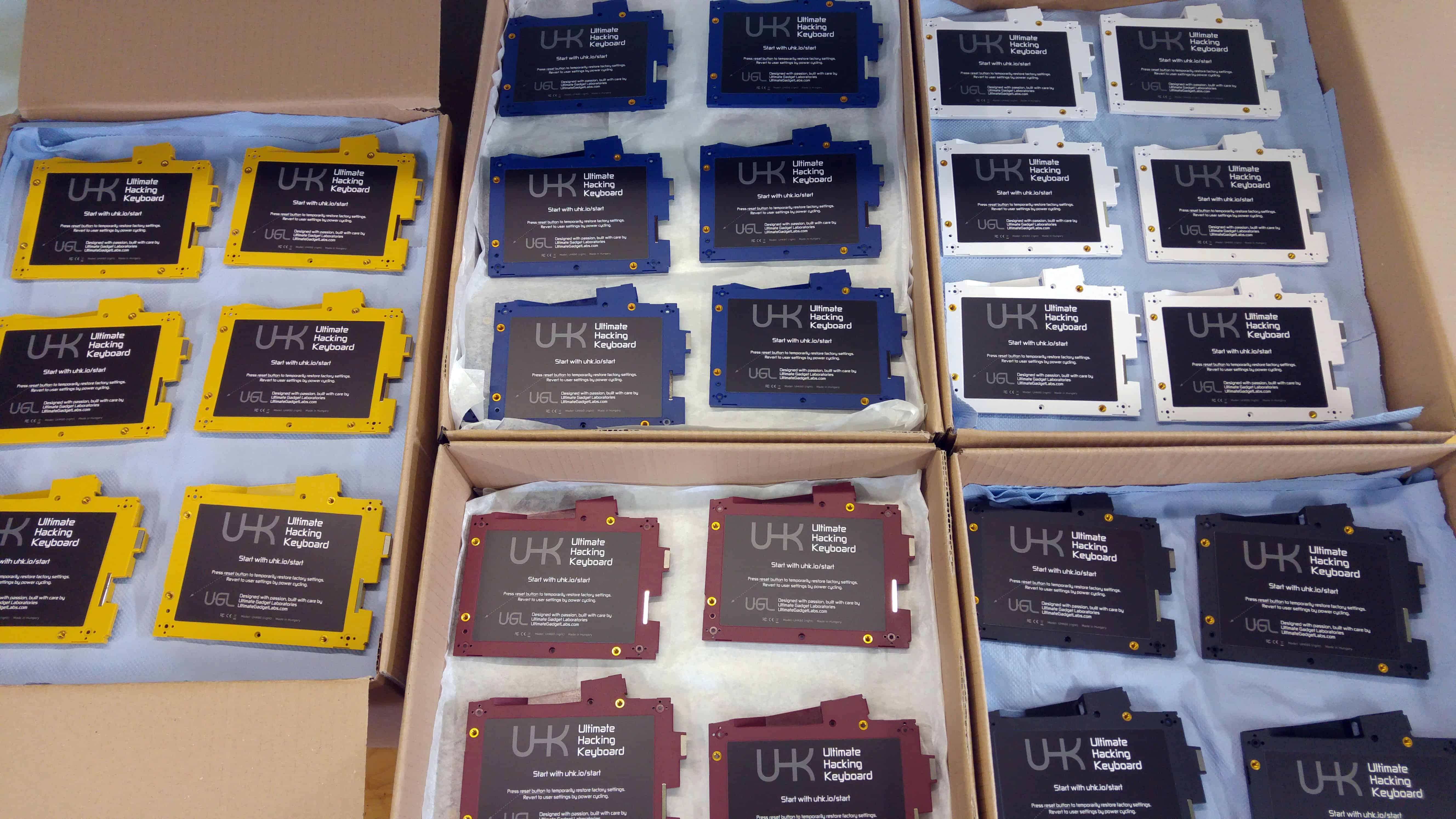
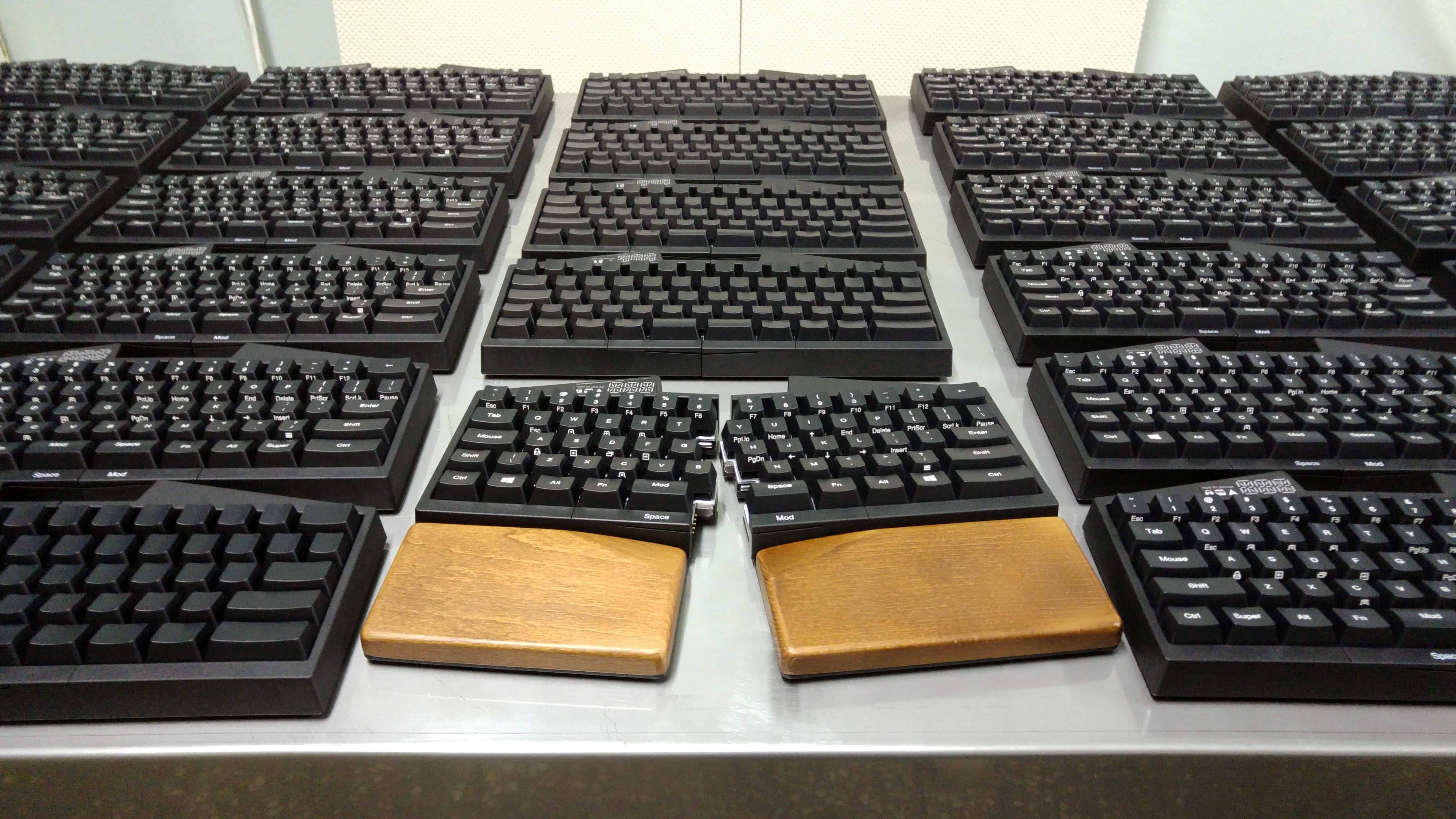
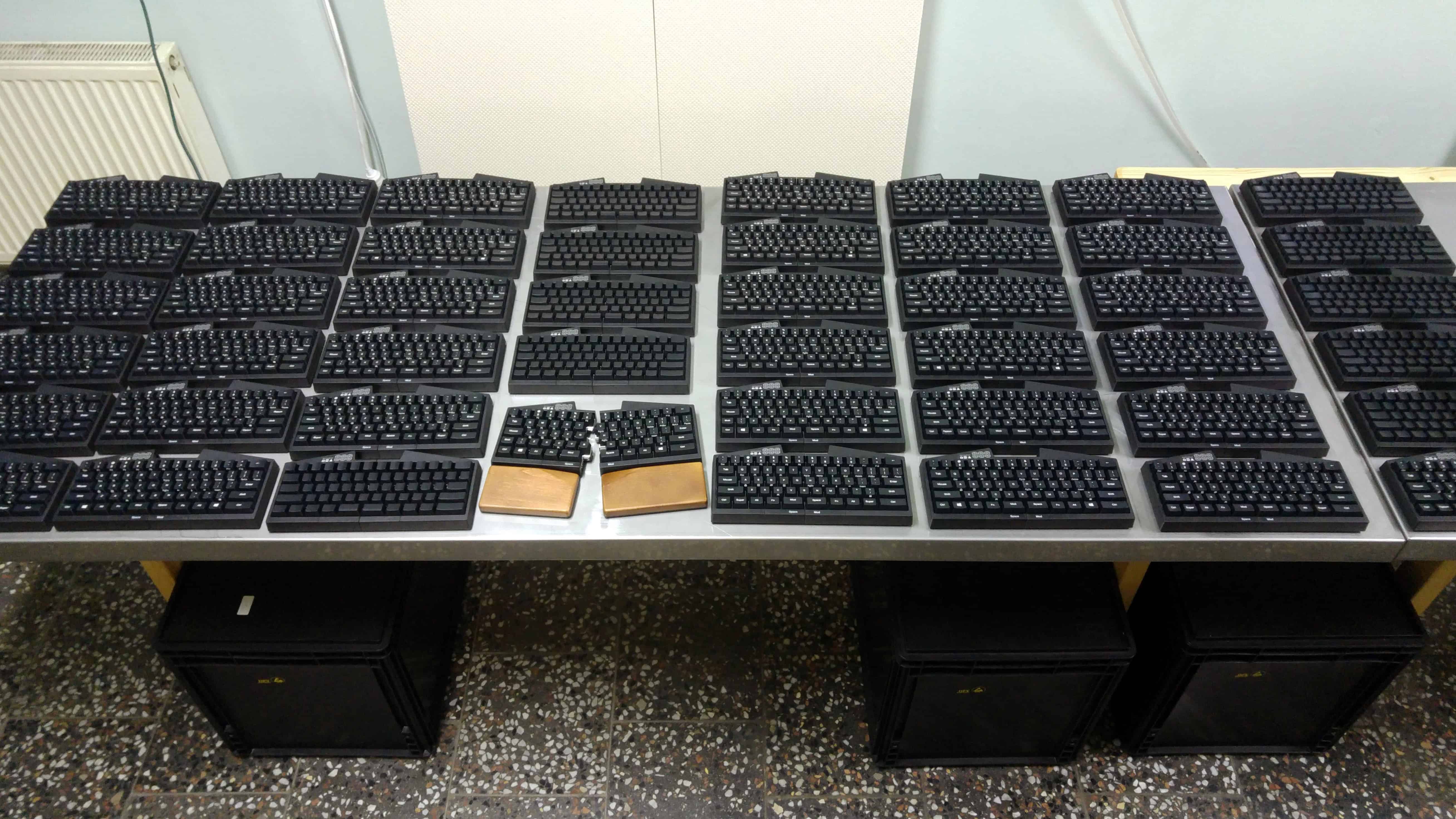
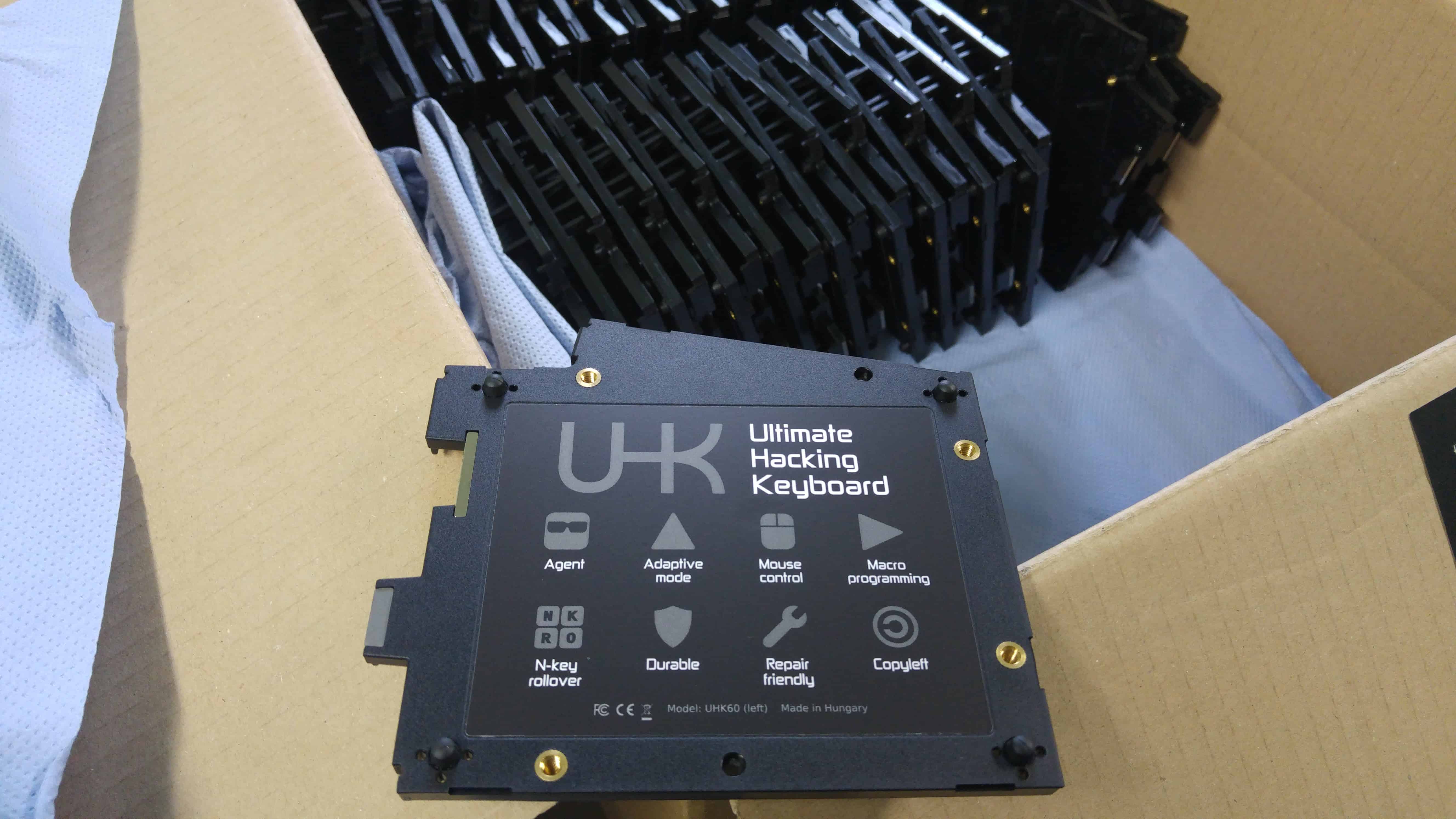
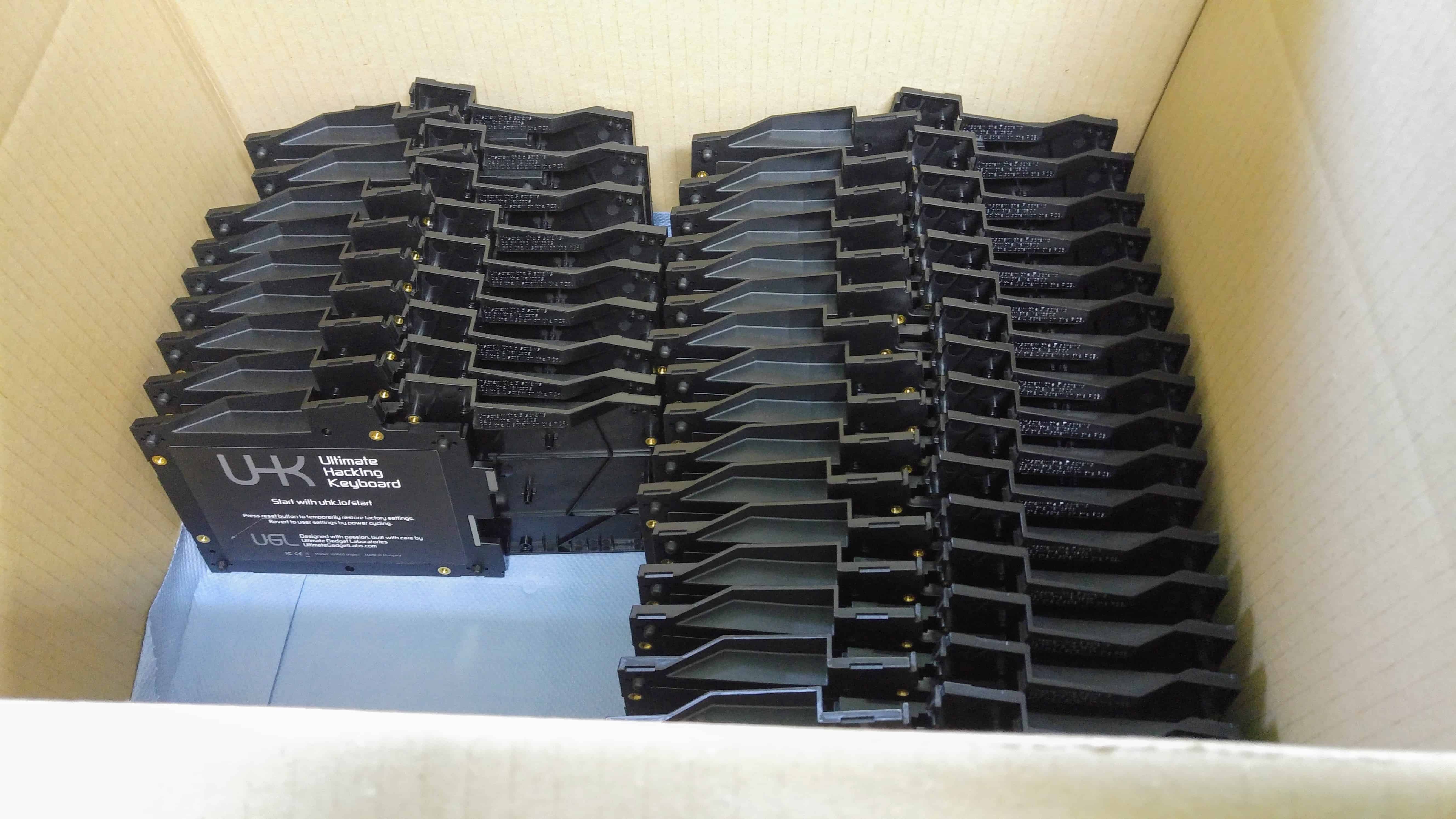
TL;DR: Our factory is up and running! According to the aforementioned delivery page, we’ve already sent out the first mini batch, so some of you should get your orders within days. Given our most recent production data, we’ll be able to deliver batch 1 of 2,000 UHKs and related accessories by the end of July. Many of you will get your orders much faster depending on your place in the queue. Everything’s looking great, and we’ll be transitioning to the modules soon.
Some UHKs of mini batch 1:
Manufacturing progress
Launching mass production wasn’t exactly a smooth ride, which wasn’t really surprising after all. Given our past experience, some things inevitably go wrong despite our best efforts.
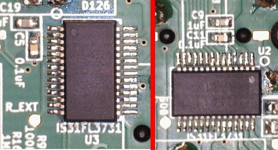
We observed that some LED segments displayed gibberish - that is, unidentifiable characters. It was quite a challenge to figure out the root cause of this, but András succeeded. Apparently, the space is very tight around the FFC cable and when the case is on, it bends the cable and some pins don’t connect. The solution? We just have to bend the FFC cables in an M shape prior to assembly.
We also noticed that some pins of some through-hole components, most notably the keyswitches and the 4P4C connectors, weren’t soldered in on some boards. We talked to our PCBA supplier who told us that their selective wave soldering machine had been misbehaving and got serviced recently. They will also use a 3-dimensional automated optical inspection machine from this point forward which should greatly reduce defects. The problematic boards will be reworked.
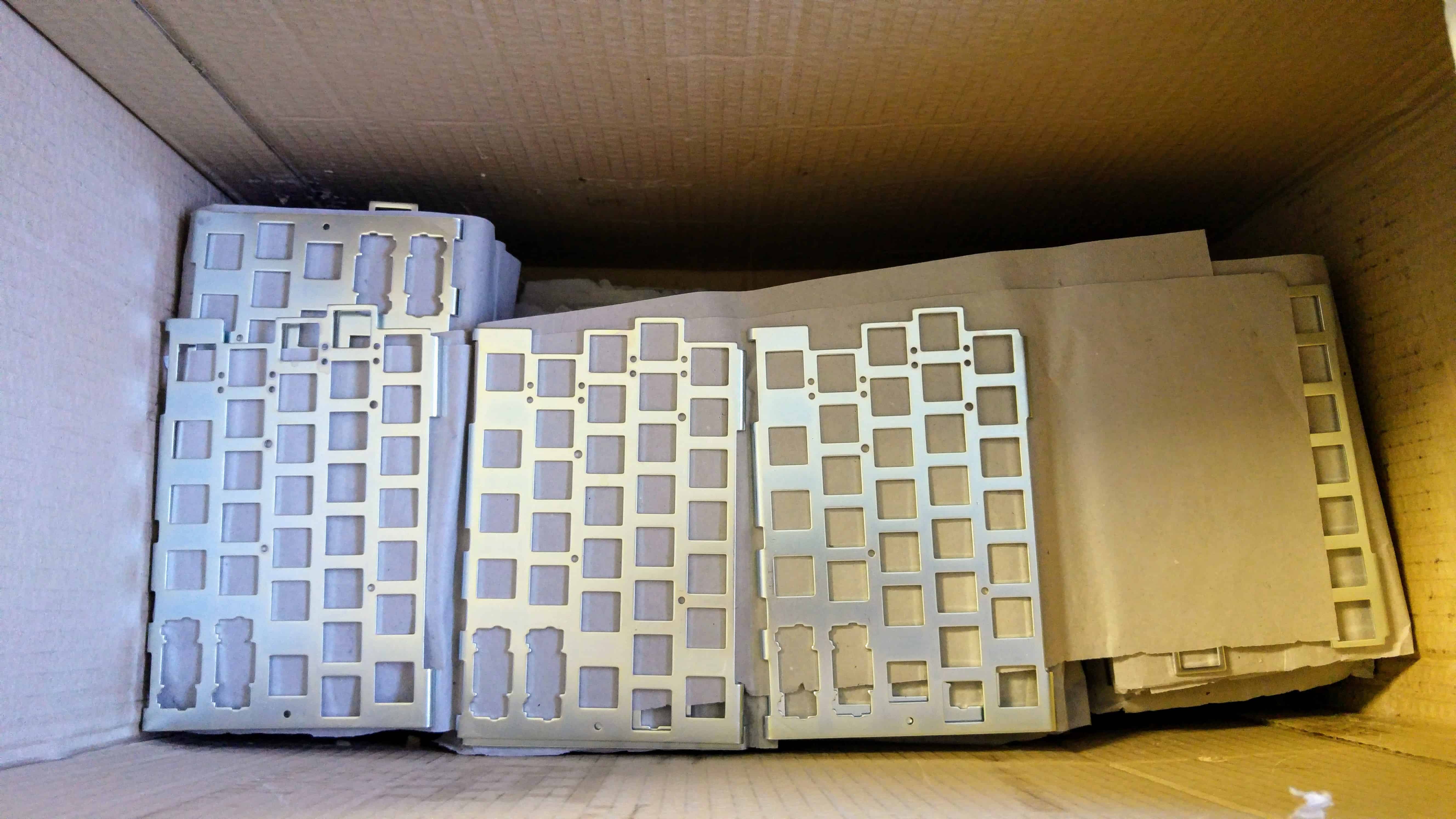
Then we were faced with a couple of bent plates. We have yet to figure out how these plates could possibly bend, but for the time being, we’ll do heavier QA until the cause is revealed and eliminated.
And lastly, a critical piece of launching manufacturing is our custom developed order fulfillment and manufacturing execution system that I’ve been working full steam on in the last couple months. It felt like building a runway while the plane takes off, but the runway has been built just in time, and now the plane is in the air.
Given the above issues, we started up slowly. According to our most recent measurements based on actual production data, we will be able to ship about two mini batches per week, which equals about 120 UHKs and related accessories. Given this pace, we’ll be able to deliver batch 1 by the end of July, so this is our current delivery target. Of course, many of you will get your orders way faster depending on your place in the queue.
Agent and firmware progress
Starting with the latest firmware, it’s now possible to wake up the host computer with a touch of a key. The LED display also gets disabled when the host sleeps to save power. See the firmware changelog and releases.
Agent got a shiny new desktop icon, it now displays the firmware versions running on the halves of your UHK, and can recover UHKs with broken configurations. See the Agent changelog and releases.
Going forward
The next big milestone is clear: the modules. The modules clearly differentiate the UHK from every other keyboard in the market, and make it the first and so far only modular keyboard ever created.
Personally, I can’t wait to control the pointer in various ways in a finer grained manner without leaving the home row, and I know that a lot of you share our enthusiasm. I’m sure the journey will be just as exciting as getting there, and as always, we’ll make you part of the journey via these updates.
Thank you for reading this update! The next one will be published on 2018-05-17. In the meantime, feel free to keep checking the delivery status page of your much awaited UHKs.
Hi there, and welcome to our monthly status update!
TL;DR: We’ve pre-assembled the parts of 2,000 UHKs. Things are progressing rapidly, but color-matching plastic parts and pad printing them accurately was more problematic than anticipated. The rejected parts are being remanufactured and are expected to be ready by next week, at which point the assembly and delivery of batch 1 of the first 2,000 UHKs will begin.
We’ve set up a dedicated delivery status page which you can check out to get up-to-date information on how delivery proceeds.
Mechanical issues
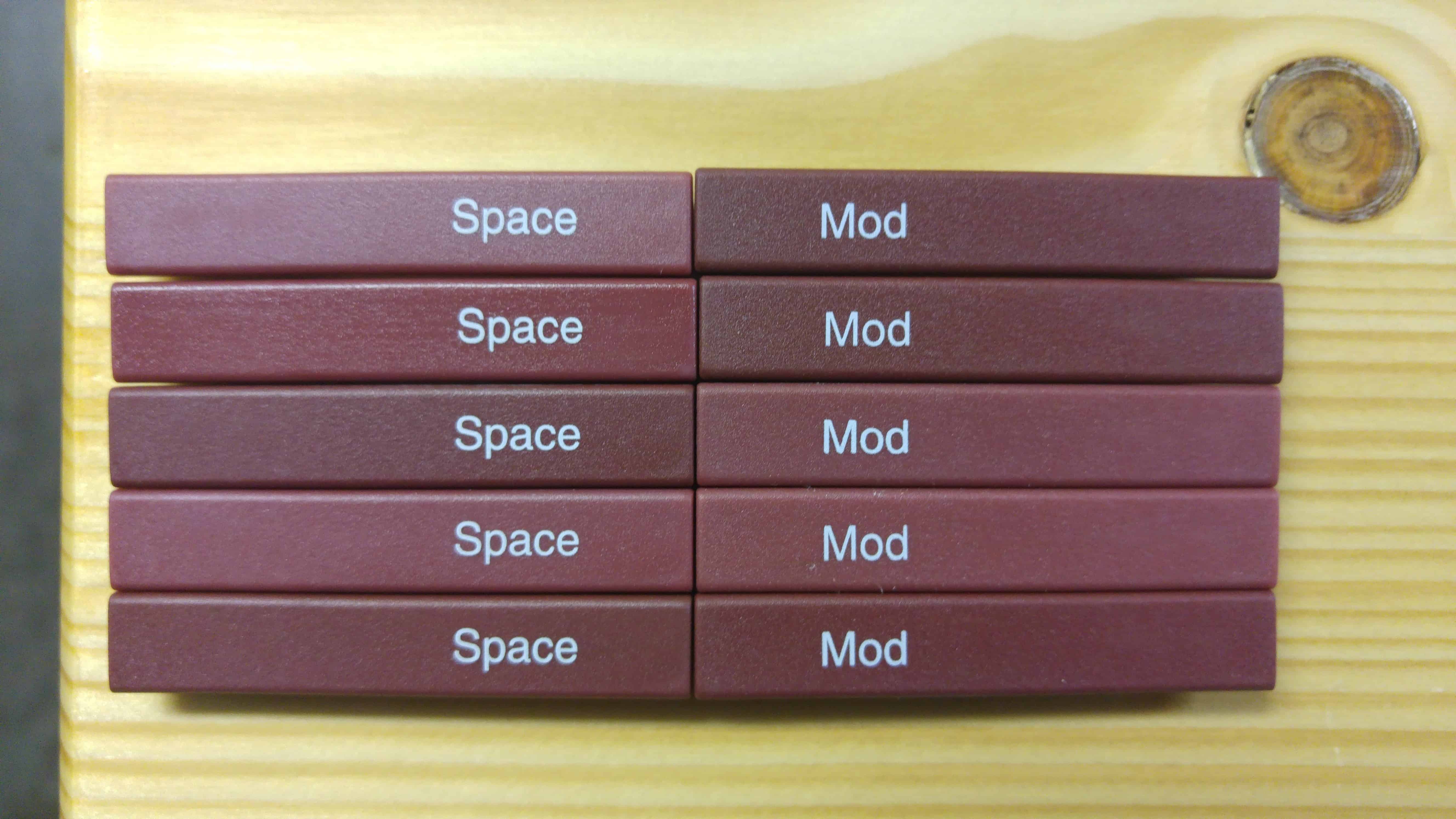
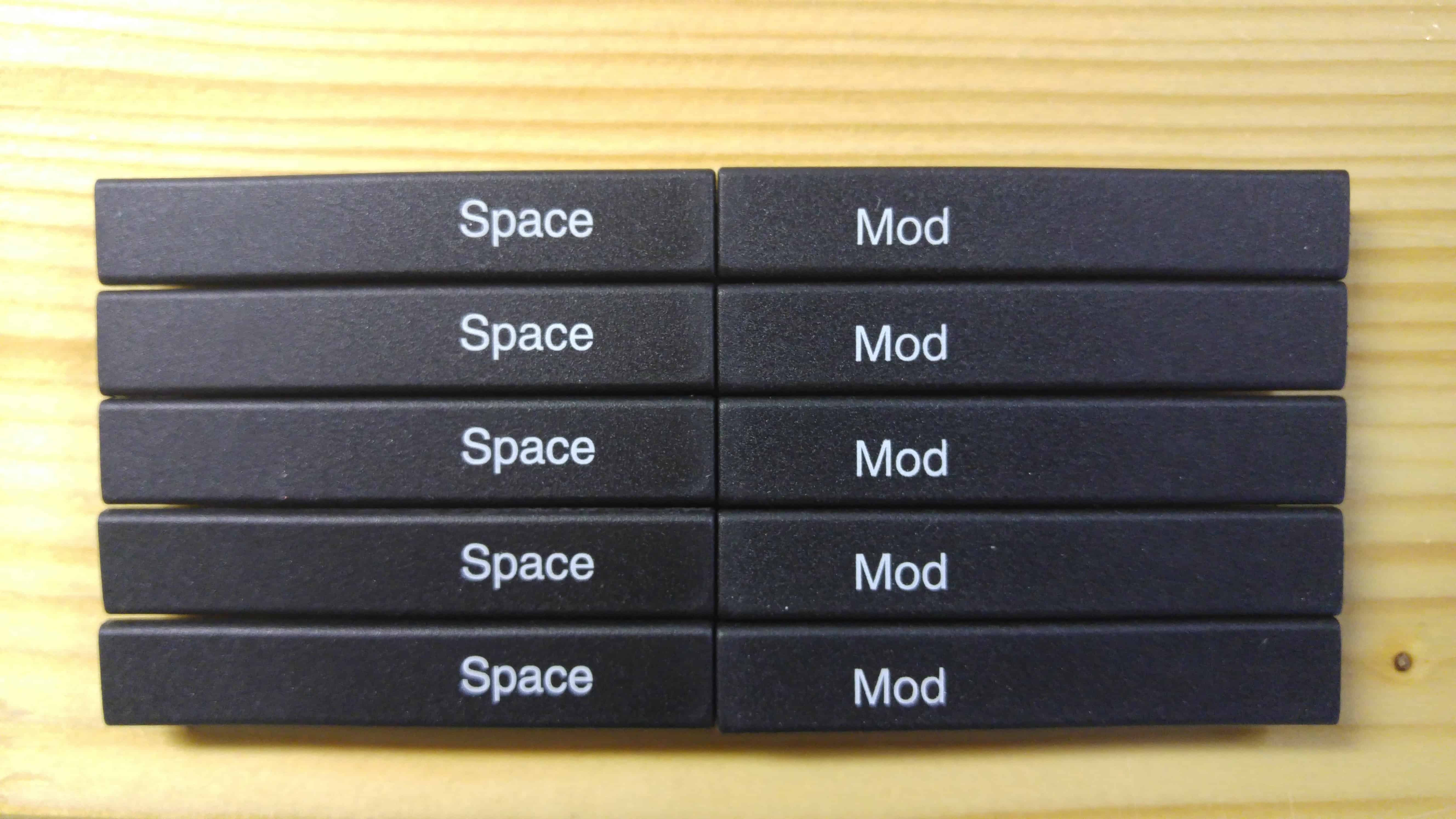
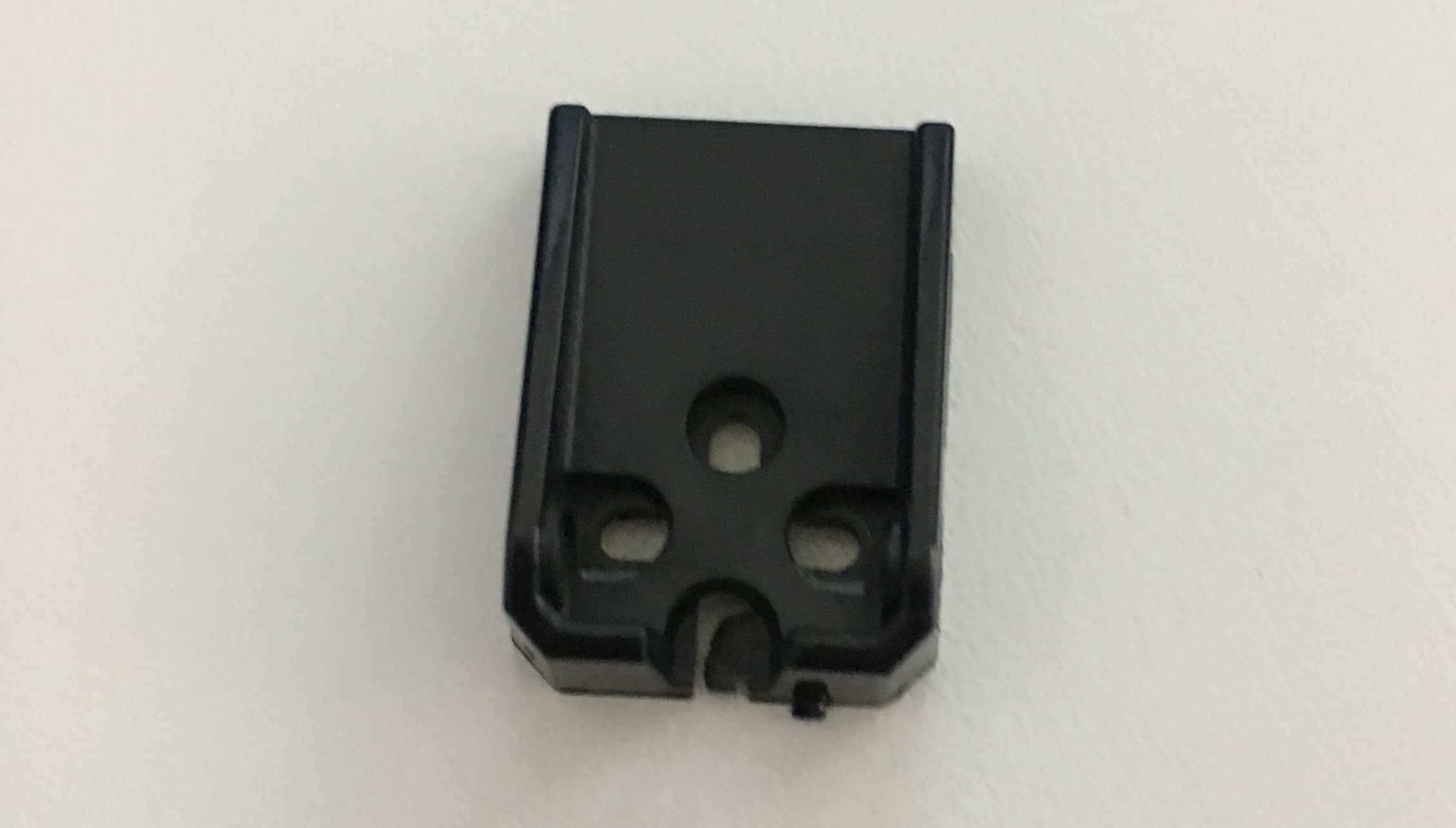
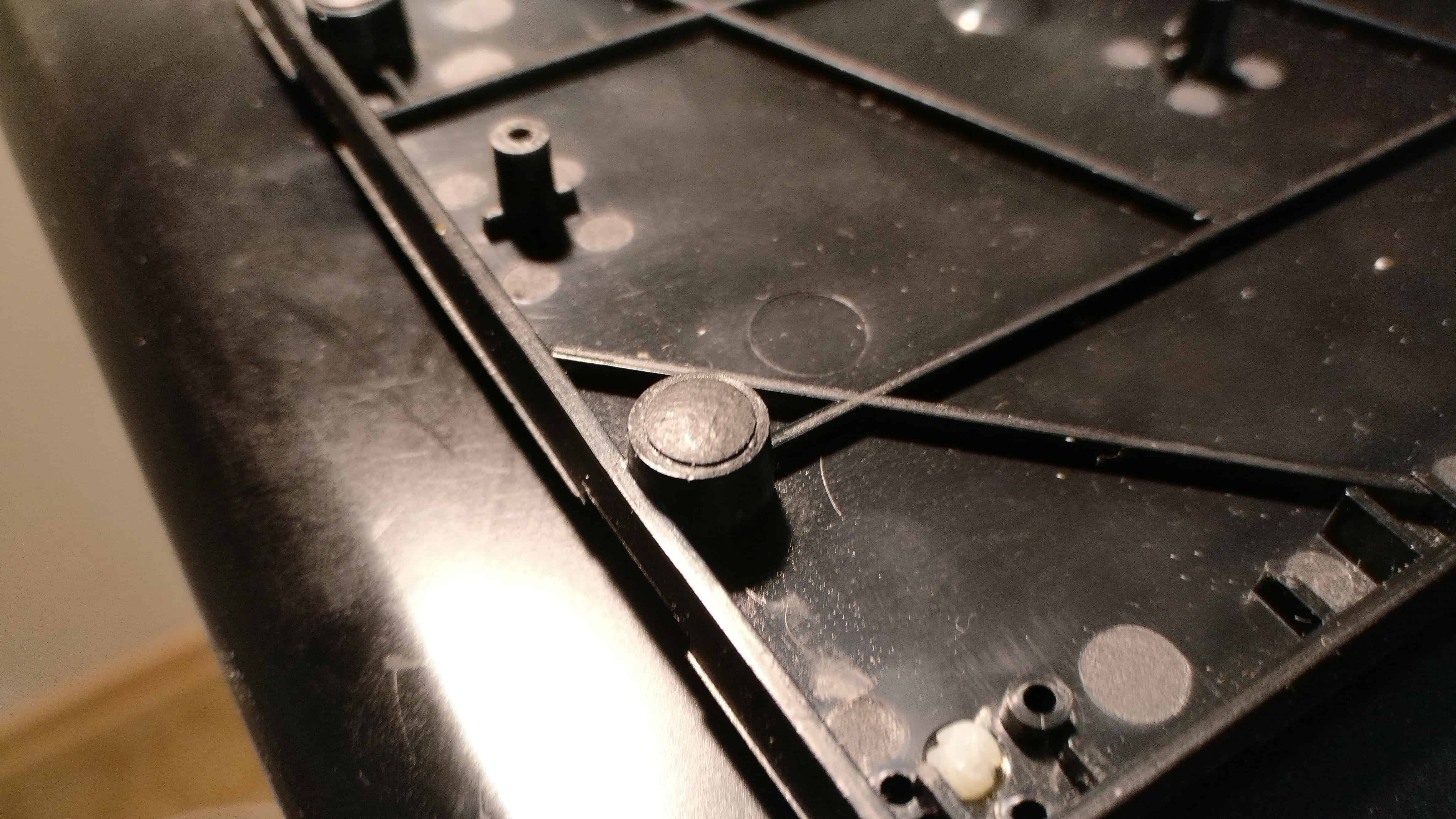
It never ceases to surprise us how seemingly mundane things can go sideways, such as color-matching, or accurate pad printing. Take a look at the following picture.
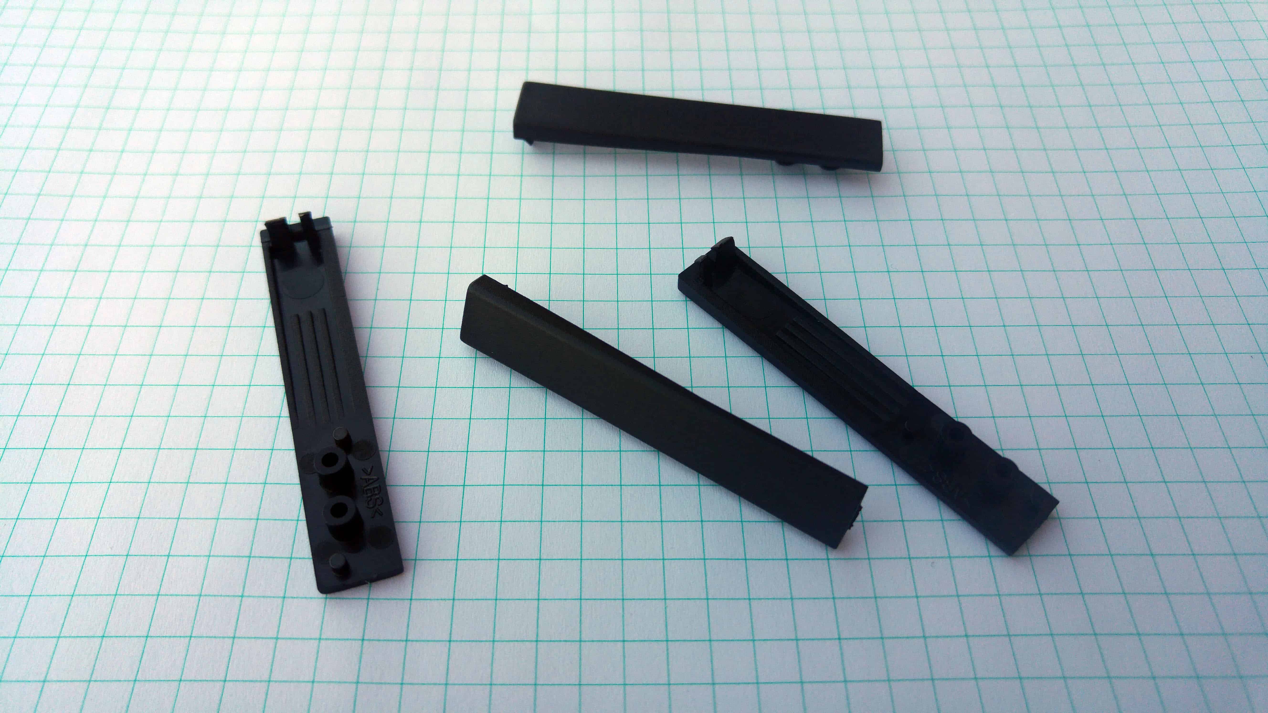
As you can see, the color of these case buttons is inconsistent. This is the first time we molded all case colors, and some mistakes were made due to lack of experience with the coloring agent. As it turned out, this is not the only thing that can go wrong when it comes to the case buttons.
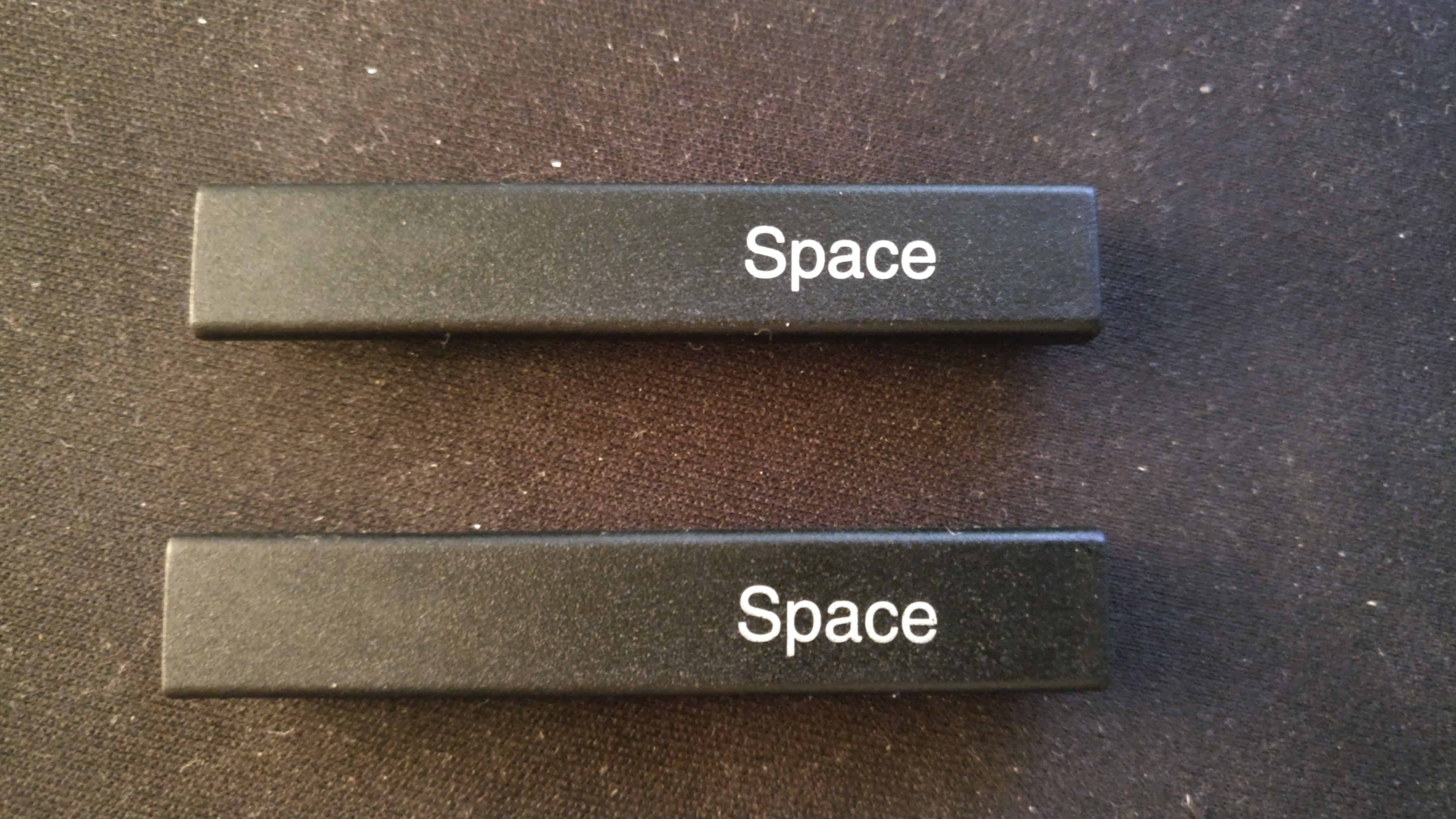
Then we observed that the vertical positions of the Space and Mod labels considerably differ because the pad printing wasn’t set up accurately.
We’ve had our fair share of WTF moments during the manufacturing process. I mean, what can possibly go wrong with seemingly trivial parts like the above? The answer is, as you can see above, a lot. And when one thing goes sideways, the delay of every relevant supplier in the chain adds up, and trivial mistakes can end up costing weeks.
The case buttons are being remolded, and they’ll be pad-printed by the next week, at which point we will finally be able to start up the manufacturing of batch 1.
Setting up manufacturing and fulfillment
As I elaborated in our previous update, all UHK option combinations considered, there are 240 different UHK types to choose from, so we have to track orders individually during the manufacturing process, which calls for a custom manufacturing system. We also purchased a fair bit of related hardware, like label printers, barcode readers, and wall-mounted displays to aid assembly workers.
Recently, I’ve been hard at work, developing our custom manufacturing execution and order fulfillment system from the ground up. It’s surely an unwelcome detour amidst of all our responsibilities, but it’s absolutely necessary, and it’ll give us a competitive edge in the long run. The system is already running well, and we’ll be able to start manufacturing next week. I’ll likely have to tweak it during this month, and afterwards we’ll finally be able to give some much needed love to the modules.
Miscellaneous
You’re welcome to check out the new releases of Agent and the firmware as some improvements have been made which you can benefit from.
Even though a lot of progress has been made since our previous update, we don’t have too much to show besides the above. According to our current schedule, batch 1 will be delivered from March to July and batch 2 will follow very closely. Again, feel free to check out our delivery status page any time if you’re interested in our up-to-date progress, and follow up on social media.
That’s it for now! Thanks for reading this update, and talk to you on 2018-04-19!
Hi there, and welcome to our monthly status update!
TL;DR: We’ve assembled 500 PCB panels, and the parts for the first batch of 2,000 UHKs are being pre-assembled. Right after pre-assembly, the final assembly of the keyboards will proceed. We plan to ship the first batch (ordered before 2017-07-13) of 2,000 UHK from March to May. Closely after the first batch, we expect the ship the second batch (ordered on or after 2017-07-13) starting from June. We’ll ship every non-module items together on a per-backer basis.
Regarding the estimated shipping dates, please note that we can’t precisely tell you when we will ship your order because we have a multi-step manufacturing process in place, and there are some variables involved. As a general rule of thumb, the sooner you ordered, the sooner we’ll deliver. We’ll send out a shipping notification email when the time comes. Also, we can’t move you ahead in the queue because it’d be unjust towards earlier backers.
Price Increases
Effective immediately, we are raising the prices of the following items:
UHK: $240
Modules: $60 per piece (no bundles anymore)
Extra UHK keycaps: $25
Extra UHK case: $25
As we elaborated in our previous update, the cause of this raise is the heavy weakening of the US dollar. We don’t plan to raise prices again until delivering all the pre-orders of both batch 1 and batch 2, at which point we’ll raise them by about 10%, which will be the final prices.
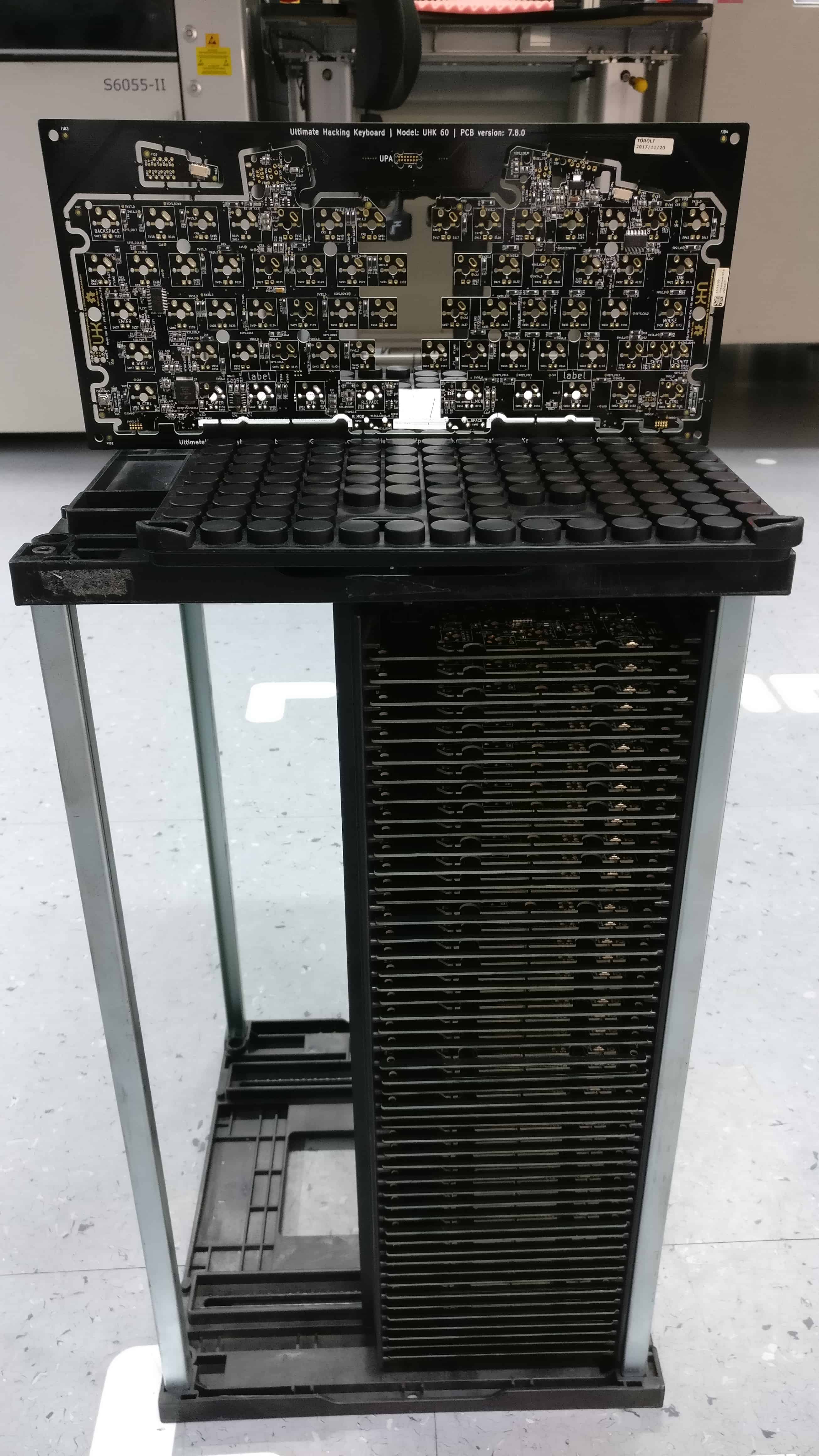
500 PCB Panels Assembled
Shortly after our previous update, we started assembling the first 500 PCB panels.
Compared to the pilot run batch of 50 panels, this was a 10x increase. Fortunately, everything went smoothly, and 500 out of 500 panels passed the test.
I was in the factory and flashed every one of these panels. I had no choice, because our custom flashing procedure and software is not sufficiently user-friendly yet. I found this experience to be extremely valuable, because now I can not only make this more user friendly in order to be able to delegate it, but also faster and more robust.
Pre-assembling UHK Parts
Currently, the parts of the 2,000 UHKs in batch 1 are being pre-assembled. After pre-assembly, we’ll be assembling and shipping every non-module orders from March to May, on a weekly basis.
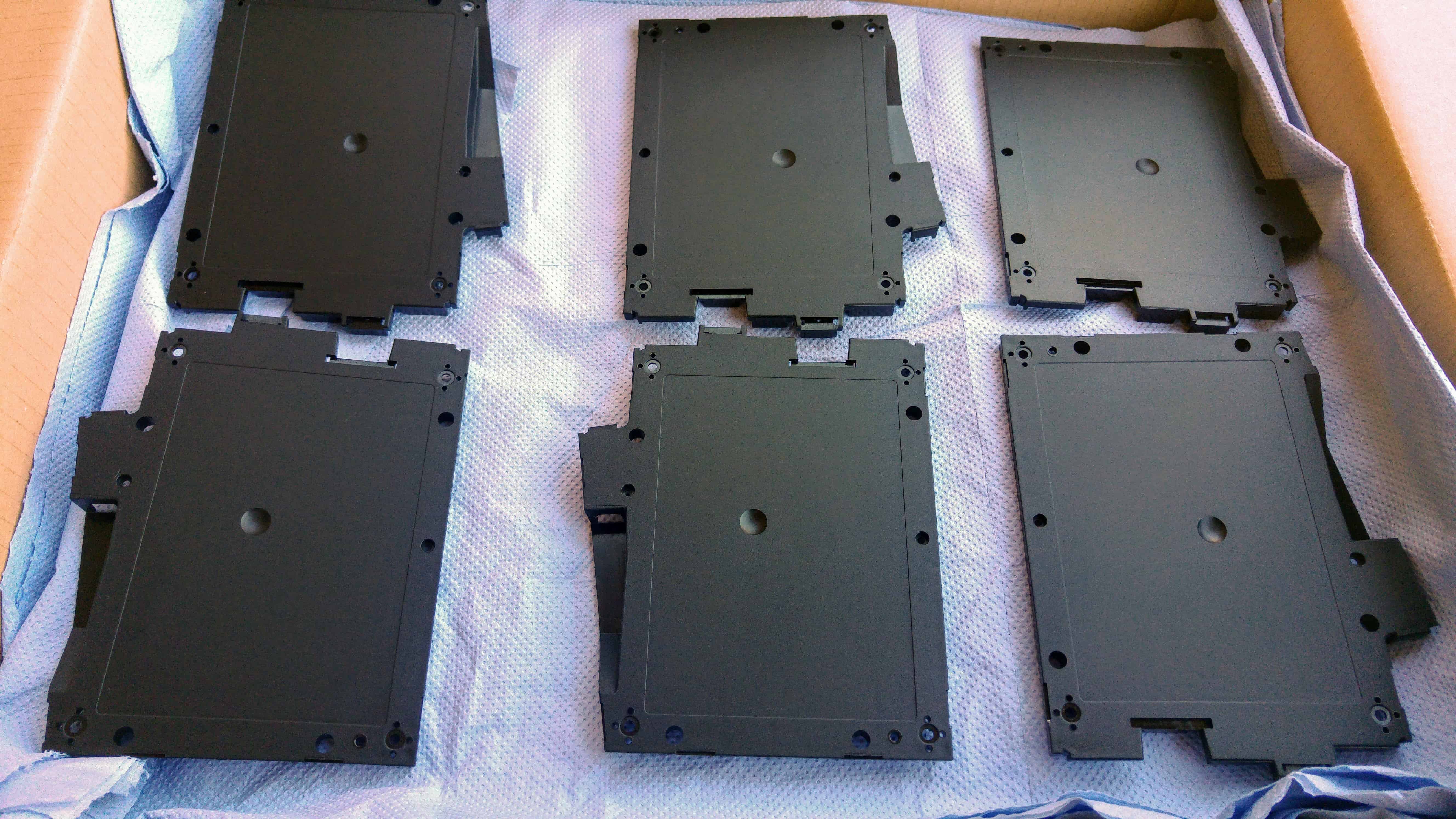
Powder-coated palm rest base platesColored cases
All things considered, we’re proceeding well with pre-assembly, although colored cases gave us a hard time. As it turned out, the coloring agent makes plastic more rigid, and it resulted in several broken cases when pushing the threaded inserts into the plastic. For the time being, we preheat the inserts before pushing them into the cases which solves the issue. In the future, we plan to slightly tweak the mold to avoid this extra step.
Another challenging aspect of the upcoming assembly process is the staggering amount of SKUs. Currently we offer 2 layouts * 5 case colors * 4 keycap printing options * 6 key switches = 240 variations, probably making the UHK the most physically configurable keyboard on the market.
Internally, we have to track every UHK to make sure that the correct options are implemented during the various assembly stages. This is vastly more complicated than offering a handful product versions, and I had no choice but to develop a custom production management and fulfillment system to deal with this situation. Some parts of the system are already working, and I’ll be focusing on this in the near future to make production and fulfillment a smooth ride.
While dealing with production, we haven’t forgotten about Agent and the firmware and we keep improving them. We released new versions recently, and you’re welcome to grab the latest Agent and flash the bundled firmware to your UHK. Also feel free to check out the Agent changelog and firmware changelog. We’ll keep making incremental improvements until we smash every bug and make the user experience heavenly smooth.
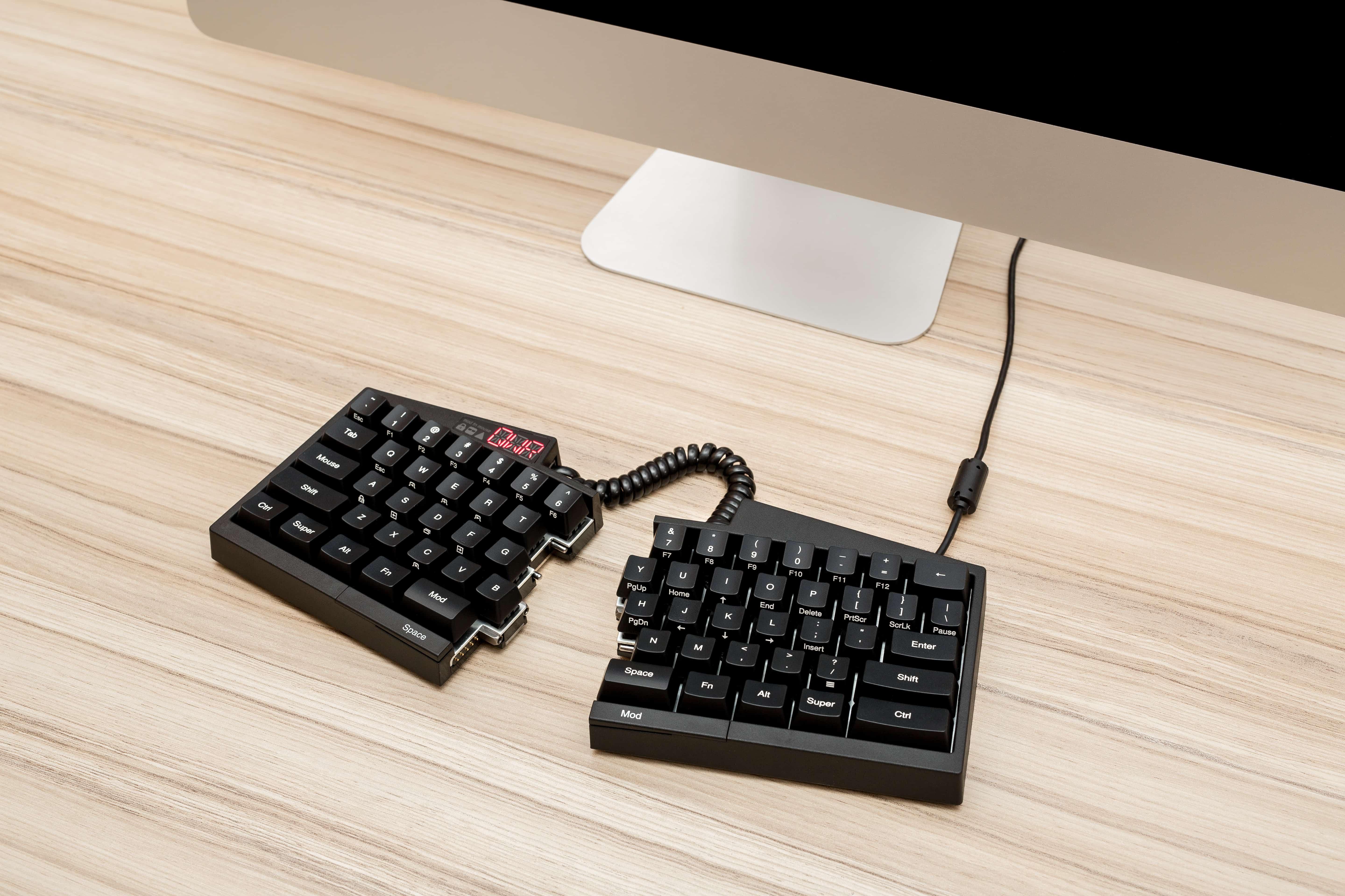
UHK Photos
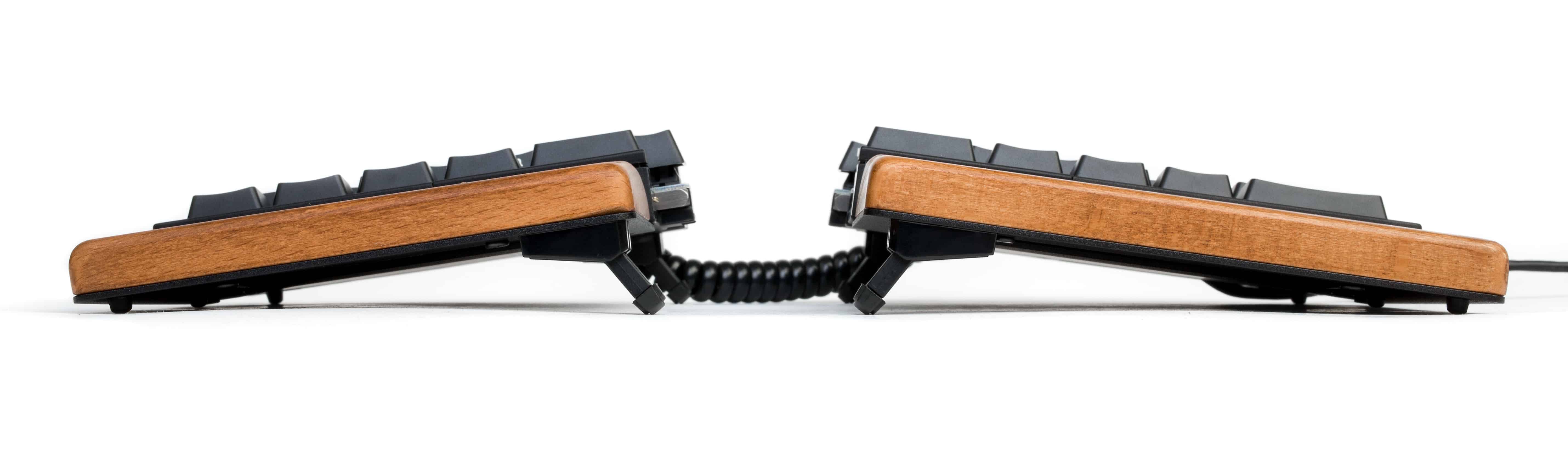
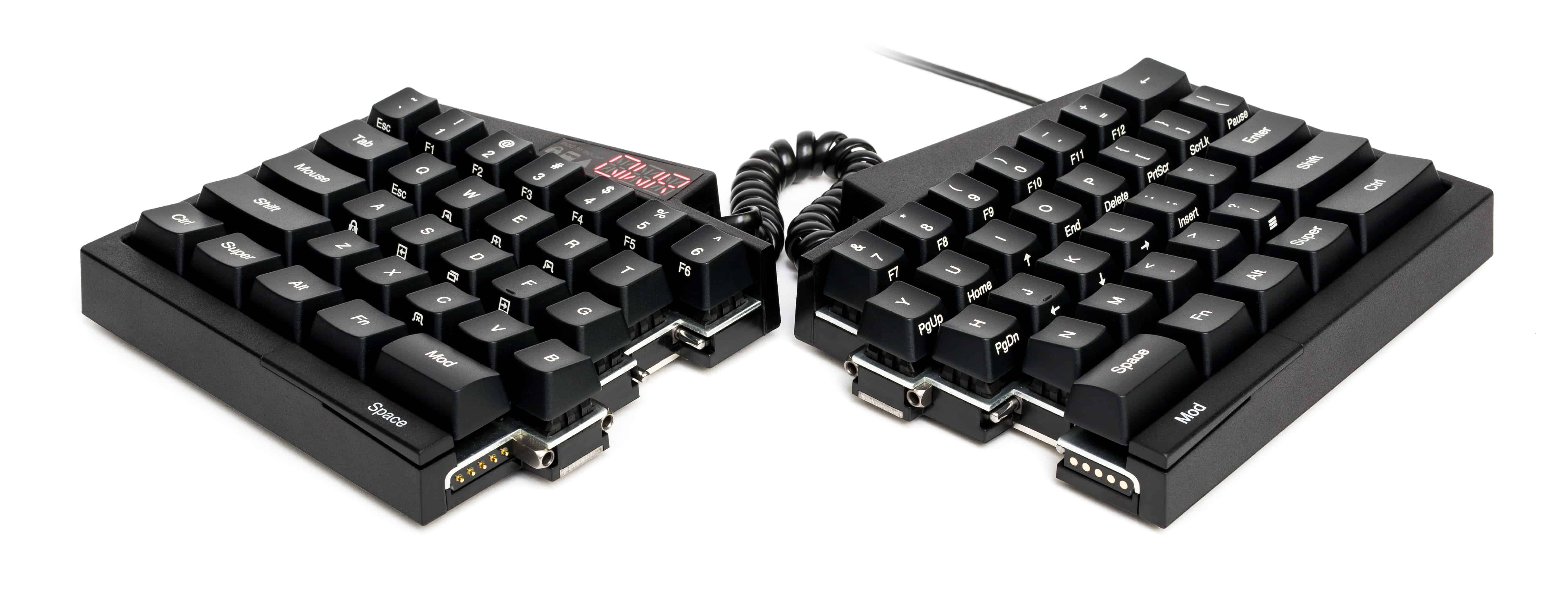
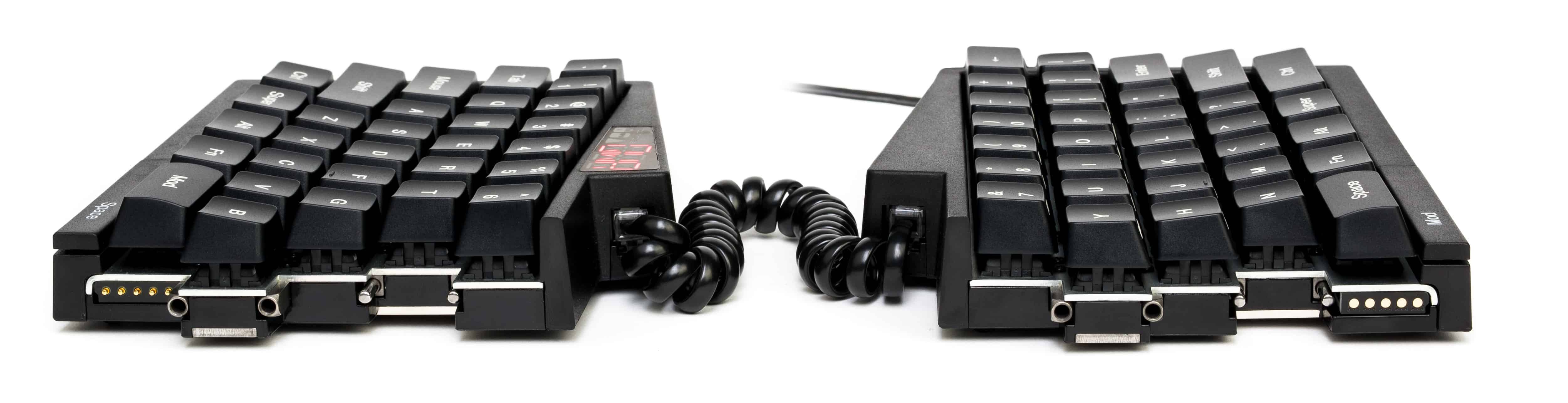
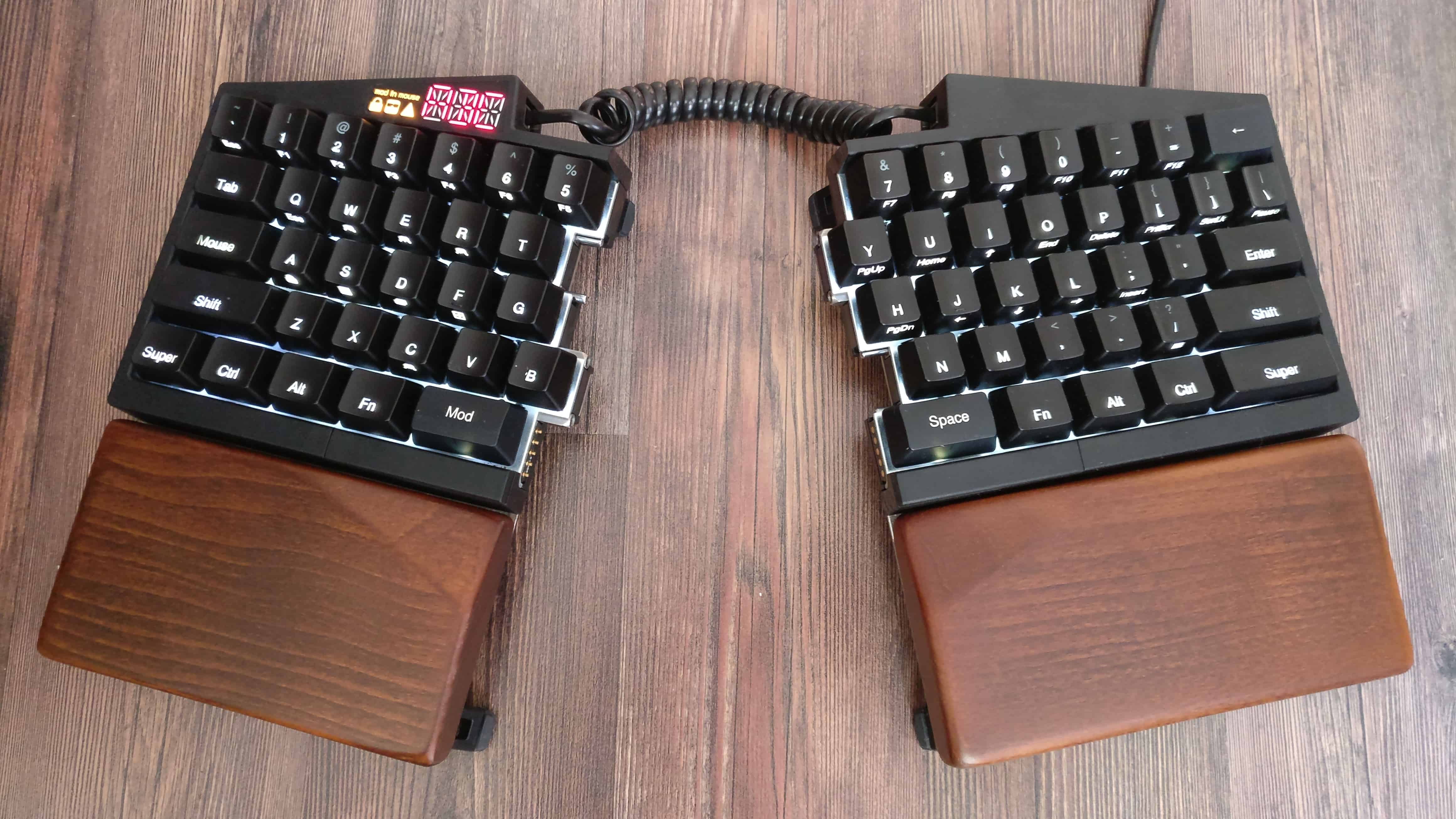
A while back, we only had photos of our prototypes, which didn’t do justice to the final product, so we took a few photos of a production UHK. We’re quite excited about these photos, and would like to show you some of them below.
And that’s it! Right now, our primary focus is the delivery of batch 1 and, closely after that, batch 2 orders. After that, we’ll focus on the modules. In true UHK style, we’ll be keeping you updated.
Thank you for reading this update, and talk to you on 2018-03-15!
Hi there, and welcome to our monthly status update!
TL;DR: The first 50 UHKs and palm rests of the pilot run were delivered, and according to the feedback we received it was a huge success! The recipients of the pilot run gave us a ton of feedback, so we’ll go over the issues they encountered, and tell you how we’ll fix them in upcoming batches. We’re raising the price of the palm rest to $55, and we’ll raise the rest of the items by 10% soon. We plan to deliver the remaining 1,950 UHKs of the first batch from February to April. We’re putting an increasingly heavy emphasis on finalizing and manufacturing the modules.
The Pilot Run Was a Huge Success
It’s one thing to design a product, and another to ship it to all over the world. András and I poured our hearts and souls into this project, we obsessed about the smallest of details, and even though we were definitely hoping for the best, we couldn’t know for sure how much you’d like the end product, so it’s safe to say that we were excited.
I’m happy to say that the feedback we received from the recipients of the pilot run was absolutely fantastic! You praised the overall build quality, the nice packaging, the onboarding experience, and the ease of use of Agent among other things.
Thanks so much for the posts, everyone! Your enthusiasm and support have been overwhelming!
Pilot Run Issues
Despite its success, the pilot run wasn’t without issues. In the spirit of transparency, we’ll go through all of the issues you encountered.
Smashed Boxes
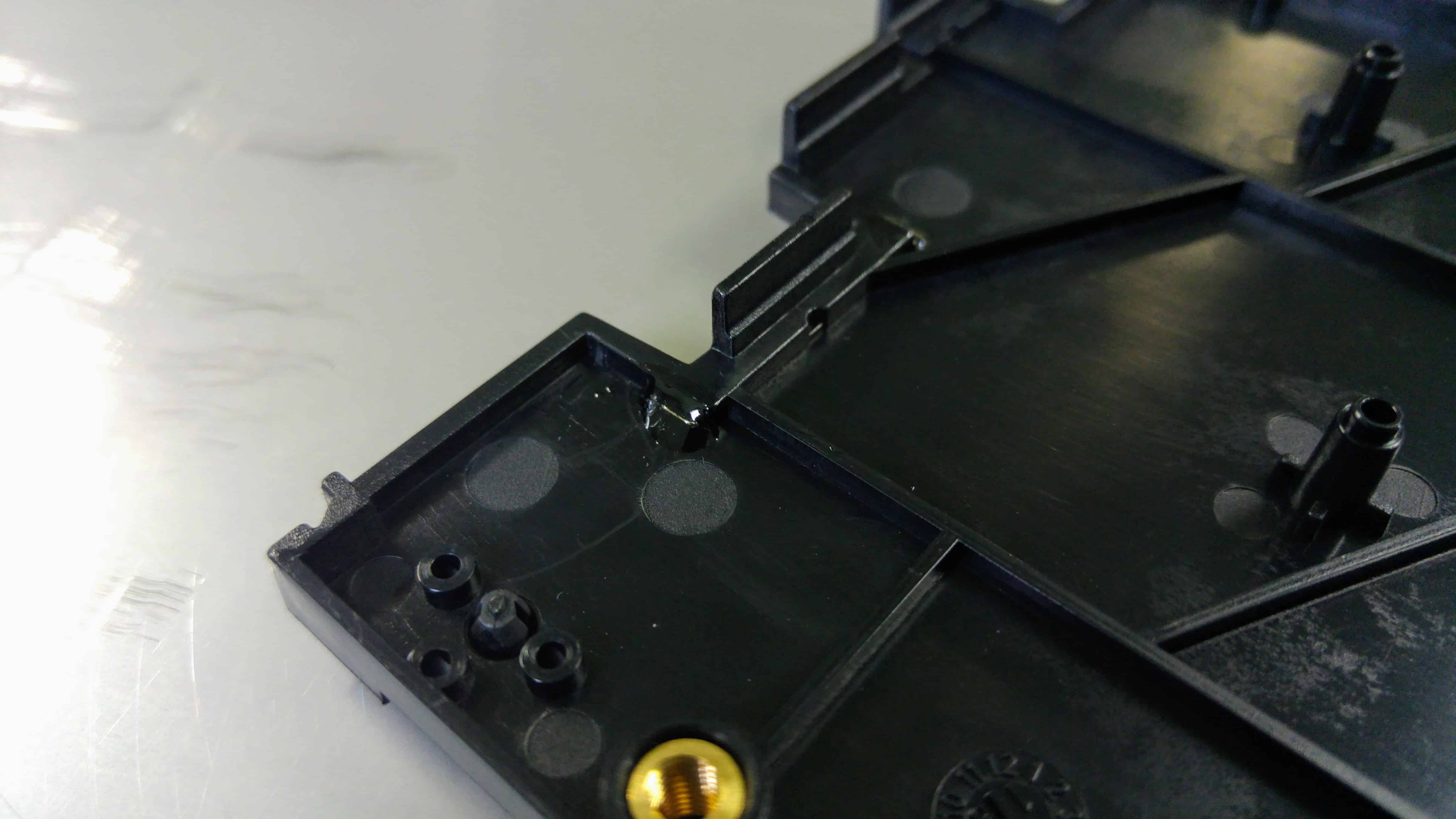
There are two small boxes within the main UHK box which got smashed on four occasions out of the fifty pilot run units. We believe that some of these occurrences went unreported, and there may be more. This is what a smashed box looks like:
We spent a ton of time and a fortune on packaging, so this is a big deal. Even worse, on one occasion, even the case of a keyboard snapped apart. Luckily, the owner managed to snap it back with a bit of pressure, but this doesn’t make the issue any more acceptable.
According to the reports we received, only USPS-shipped UHKs were affected. We’re not sure whether it was due to the holiday madness, or if it’s a general issue, but we reinforced the boxes, which will hopefully resolve this issue in the long run.
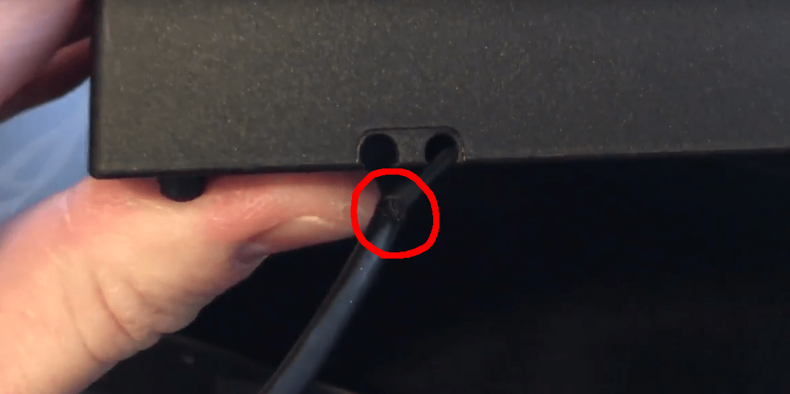
Sharp USB Cable Recess
There are two recesses in the case which hold the USB cable and they’re way too sharp and chew up the USB cable quickly.
The mold has already been modified, so the edges should be smooth going forward. A backer reported that he easily managed to sand down the sharp edge, resolving the issue in no time. If you’re affected, you might want to do the same, but if you want a replacement case, please just let us know.
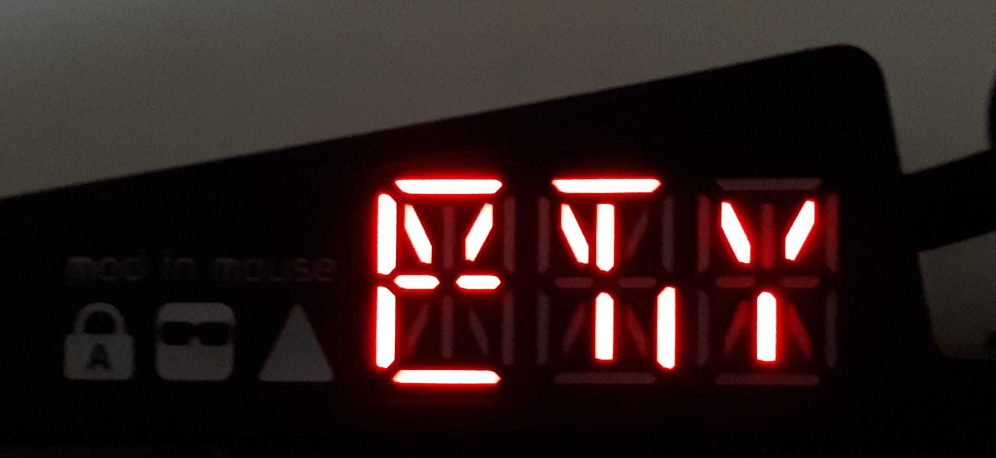
Loosely Connected LED Display
Some of you reported strange artifacts appearing on your LED display, which is a sure sign of a loose FFC cable.
The FFC cable connects the display with the left main board. Apparently, we could have done a better job connecting them during the assembly process. As a result, the cables of two UHKs got loose during shipping. We’ll try our best to more thoroughly assemble future batches.
This issue called for our first ever repair guide. We have already emphasized the importance of repair before, and this was the golden opportunity to follow our words up with action. Both affected backers were able to fix the issue using the guide and they even contributed to it. Thanks so much!
Just to get things straight, we don’t expect anybody to repair his/her UHK, but the opportunity is there, and we encourage repair in general. It’s certainly much faster than sending it back and forth to the other side of the world, and especially useful after the warranty period is over.
Feet Molding Issues
On two occasions, visible artifacts were noticeable on some feet.
This is clearly an injection molding issue. We’ll do heavier QA in this respect.
Software and Firmware Issues
A number of issues have been reported recently in the firmware and agent repos. The vast majority of these issues are not critical, but they affect usability in one way or another.
Understandably, we’ve been mostly busy with the critical issues. The most critical was a firmware issue that made the UHK freeze after a while. This was really annoying because it was super hard to find the root cause of it. Luckily, it looks like we’ve been able to resolve this, and it shouldn’t affect more people.
There was another critical issue in which the left keyboard half got bricked during the firmware update process. I’ve made the update process more robust, and improved the update script, which unbricked the unit. This script feature will be integrated into Agent soon. The UHK should very rarely get bricked, and when it happens it should always be unbrickable.
Going forward, we’ll be addressing all of the issues of the agent and firmware repos, but there’s a lot on our plate nowadays, so some may take a while. We’re doing our best.
All Hail Our Contributors
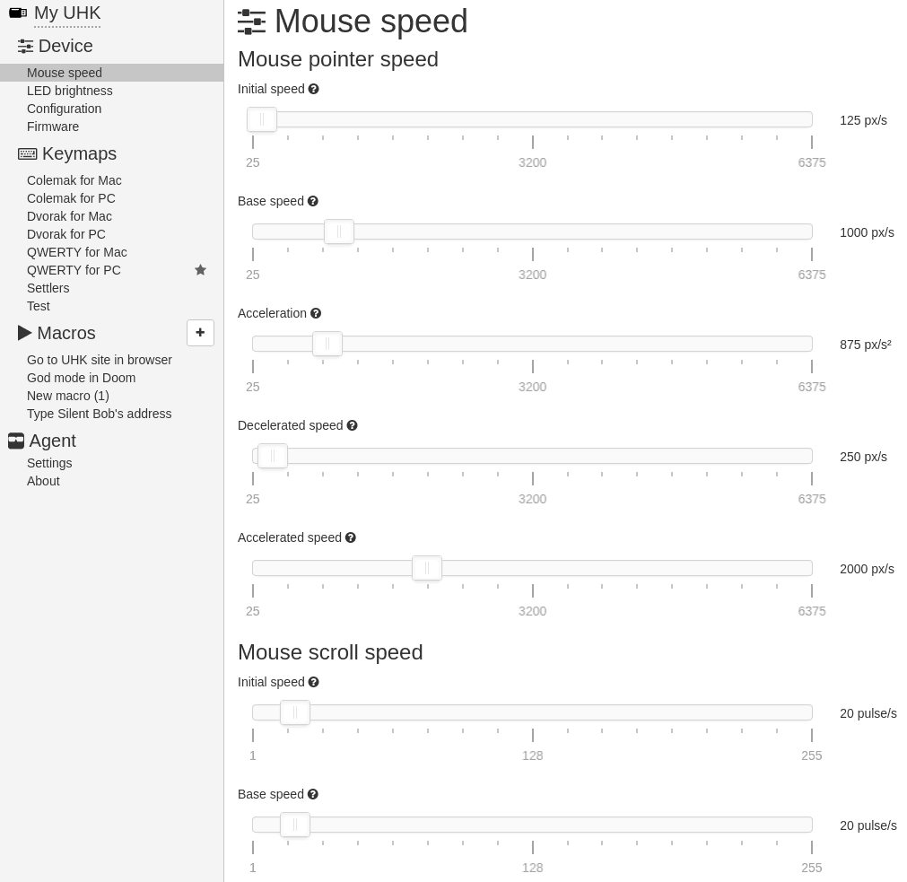
Mikko Lakomaa, an early contributor of ours, switched into high gear after receiving his UHK, and implemented two much-welcomed issues. Thanks to the fruits of his labor, now we can adjust mouse speed and LED brightness via Agent.
Thanks so much for your contributions, Mikko! It’s nice to see Agent improving so rapidly.
Price Increases
Effective immediately, we’re raising the price of the palm rest to $55, and we’ll raise the rest of the items by 10% soon. Let me explain why.
When we originally envisioned the UHK palm rest, its design wasn’t finalized, and we weren’t sure about the materials and technologies we’d ultimately use to craft it. We were also unfamiliar with the costs involved. As the design progressed, we were consistently moving toward an increasingly high-end, premium product which inevitably added to its cost, so much so that up until this point we haven’t had any profit on the palm rests when selling them for $30.
For what the palm rest is worth, $55 is still a bargain considering the market prices. If you search for “wooden wrist rest”, $40 is a usual price tag, but those palm rests are made of one wood piece, not two pieces, don’t feature powder coated black plates, and their geometry is less ergonomical (simpler, thus cheaper to machine) than the UHK palm rest.
Eventually, we’ll further raise the price of the current wooden UHK palm rest to about $80 which is a reasonable market price, but before doing so, we plan to offer a less premium, and more affordable palm rest in addition to the current wooden palm rest.
We’ll also soon raise the price of the other items by about 10%, including the UHK, extra keycap sets, extra cases, and the modules. This is justified by the heavy weakening of the US dollar during 2017. We pay our suppliers primarily in Hungarian forint, so this very much affects us. 10% is actually less than the weakening of the dollar which is about 15%, so we’re trying to not raise prices too heavily.
Nobody likes price increases, but we’d much rather take this route than sacrificing quality, or allocating less funding for R&D. We hope you understand and resonate with our mindset.
Expected Delivery and What’s Next
Going forward, our most immediate goal is to deliver the remaining 1,950 UHKs and accessories (everything but the modules) of the first batch. We expect to deliver these items from February to April, and then the second batch will closely follow.
Our assembly operation is admittedly micro-scale compared to the assembly lines of China. As we previously stated, instead of hiring a Chinese OEM for assembly, we opted to set up our own assembly line in Hungary and operate it in the long term. This has numerous benefits, like rigorous QA and direct control, but the downside is that the throughput of this line is rather low.
It wouldn’t make sense to massively scale up production because the accumulated preorders translate to a huge peak regarding assembly. It’ll considerably settle down after delivering the pre-orders, so hiring a bunch of people only to fire them soon afterwards doesn’t seem like a good idea.
We plan to keep assembly going continuously, and ship so-called mini batches on a weekly basis. We’ll remind you in a future update to change your shipping address before orders start going out, but please do check/change your current address by going to your Crowd Supply account.
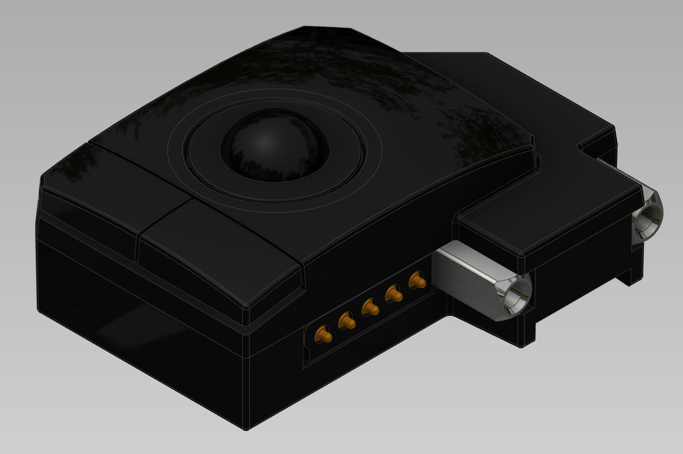
As for the modules, fear not, we didn’t forget about them. We’ll be allocating more and more resources to finalize and manufacture them. András has been working on them recently, and this is the latest, and probably final design of the trackball module.
I think András did a great job designing this module. I cannot wait to see it work and give it a whirl (pun clearly intended).
Thank you for reading this update! We hope you enjoyed it, and we’re excited to talk to you on 2018-02-15.
Hi there, and welcome to our monthly status update!
TL;DR: The 50 UHKs of the pilot run and their palm rests have been assembled and will be shipped on Monday. We’ll ramp up production afterwards, and continue the fulfillment of the rest of the crowdfunding starting in January.
Examining the First Samples
Before the pilot run assembly, our contractor assembled four UHK panels, so that we could examine and approve them. We’ve taken a thorough look at them, and I noticed that the 4P4C jacks didn’t seem right. An older version of the jacks was used which we replaced a while ago with another jack. The spiral cable could not be removed from the older jack because its plug was too deep in the jack when the UHK was fully assembled, which is why we changed it in the first place.
Our contractor originally ordered the correct part, but the component distributor quoted an alternative replacement part and didn’t explicitly tell our contractor of the change. It’s pretty hard to spot these replacements in a long component list, hence the wrong part was ordered.
This miscommunication error cost us a couple days to get replacement jacks, but luckily no other issues were found.
PCB Assembly
The next step was SMD assembly which went very smoothly. This is a short video of the process:
As you can imagine, there are a number of steps involved in this process:
The boards go into a solder paste stencil printer machine which applies paste to the pads where the surface-mount components will connect.
The applied solder paste gets inspected by a solder paste inspection (SPI) machine that creates a 3D model of the paste to make sure that it has been correctly applied where needed.
Here come the pick and place machines, which place the tiny surface mount resistors, capacitors, diodes, ICs, and other devices onto the board. All three of our contractor’s pick and place machines were operating simultaneously, which is not really justified for the UHK, but it allows for larger throughput. The machines are usually so fast that their movements can barely be seen by the naked eye, but this time they were operating much slower than usual so that operational tweaks can be made as necessary.
At this point, the boards go through a reflow oven. The oven has multiple zones, each featuring a different temperature according to the specified temperature profile. By the end of this step, the solder paste solidifies, and the components are affixed to the board.
Normally, the boards are inspected by an automatic optical inspection (AOI) machine at this stage, but the process parameters are not fully finalized yet, so a human operator inspected the boards manually.
Finally, the boards are sent to my station where I flashed them on my Raspberry Pi workstation, with a UHK, of course.
The boards not only look beautiful, but they all work perfectly. This is a pretty good start.
We left the boards at our contractor to get the through-hole parts soldered, and some days later they sent us the fully assembled panels.
Mechanical Assembly
Unlike the PCB assembly, the mechanical assembly is a fully manual operation. It involves breaking out the PCBs from the panels, placing the panels into the pre-assembled bottom cases, screwing the metal guides to the plates, assembling the top and bottom cases, and putting the keycaps on the key switches. The result is 50 beautiful pilot run UHKs, ready to be shipped.
Shipping Status
Right now, we’re working on assembling the palm rests, and on Monday the UHKs and palm rests of the pilot run will be shipped. Exciting times!
Being located in Hungary, the first UHKs of the pilot run are expected to arrive in Hungary, then to the rest of the EU, then to the US, then to the rest of the world. We deliver the EU units directly, and the non-EU units via Crowd Supply (based in the US). We can’t change this in any way, or ship directly to everyone due to accounting reasons. Please note that except for the above, we do ship on a first come, first served basis. You will receive a shipping confirmation email with a tracking number from Crowd Supply when you order ships. If you need to change your shipping address, do so now through your Crowd Supply account. For questions on shipping, see The Crowd Supply Guide.
We’re hoping that most, or all of the pilot run UHKs will arrive before the holidays, but being just before the holiday season, we’re not sure.
Starting in January, we’ll scale up production and plan to fulfill the first batch of orders in 1-2 months. Afterwards, the second batch will follow. We’ll be keeping you up-to-date.
Thank you for reading this update! We wish you a Merry Christmas and Happy New Year, and we’ll talk to you on 2018-01-18.
Hi there, and welcome to our monthly status update!
TL;DR: We’ve passed both FCC and CE! We’re assembling the PCBs of the pilot run next week and shiping the first pilot run of 50 UHKs around the end of November. We’ll do our best to start to delivering the rest of the UHKs in December, but we may slip to January due to the holidays.
CE passed
We assumed that CE is a piece of cake after we passed FCC so easily, but as it turned out, it wasn’t a walk in the park at all. First, I got a message from TÜV Netherlands saying that we failed CE. They shot one of the UHK prototypes with an ESD gun at the bronze inserts in the back. A discharge of -6kV made the prototype permanently dysfunctional.
Given that FCC was already done by TÜV Netherlands and TÜV Hungary is entitled to certify CE, I called back both prototypes to Hungary. Upon arrival, I investigated the failed one, and saw that the microcontrollers in each half and the FB7 ferrite bead of the right half were fried. After replacing these parts, the prototype was perfectly functional again.
In order to prepare for the next CE test, András fabricated a couple of rubber caps which I glued to the bronze inserts inside of the plastic case to isolate them from the PCB.
Armed with this fix, we went to TÜV to conduct the next test.
Oddly, not only the sealed inserts passed the test, but the non-sealed inserts, too. We couldn’t reproduce the issue that TÜV Netherlands hit, but we found another one.
When Balázs shot the magnet of the right half with the ESD gun, the prototype failed. The lights went out, and operation could only be restored by power cycling the prototype. Even though it’s not a terminal failure, according to the standard, this is a fail.
We came up with an idea on the spot: insulating tape. We stuck some tape to the ends of the right magnet inside of the case which made the prototype hardly ever fail. This wasn’t a sufficient solution because the magnet had to be better sealed. We figured that epoxy should work really well because it withstands 11 kV/mm, and just as assumed, it did solve the issue indeed.
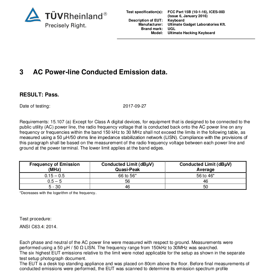
This is the preliminary CE pass for your viewing pleasure:
And this is the pass section of the official FCC certification:
Ultimately, we’ll modify the molds to seal the magnets with plastic. ABS withstands 20 kV/mm, so it’s an even better insulator than epoxy, and we won’t have to apply drops of epoxy during the assembly process. Until the molds get modified, we’ll apply epoxy to the current cases that we ship to the EU (CE being EU-specific).
Now that we’ve passed both FCC and CE, we’ll launch PCBA very shortly. Our PCBA contractor is eager to start. Surface-mount assembly is scheduled for next Monday, through-hole assembly is scheduled for later in the same week.
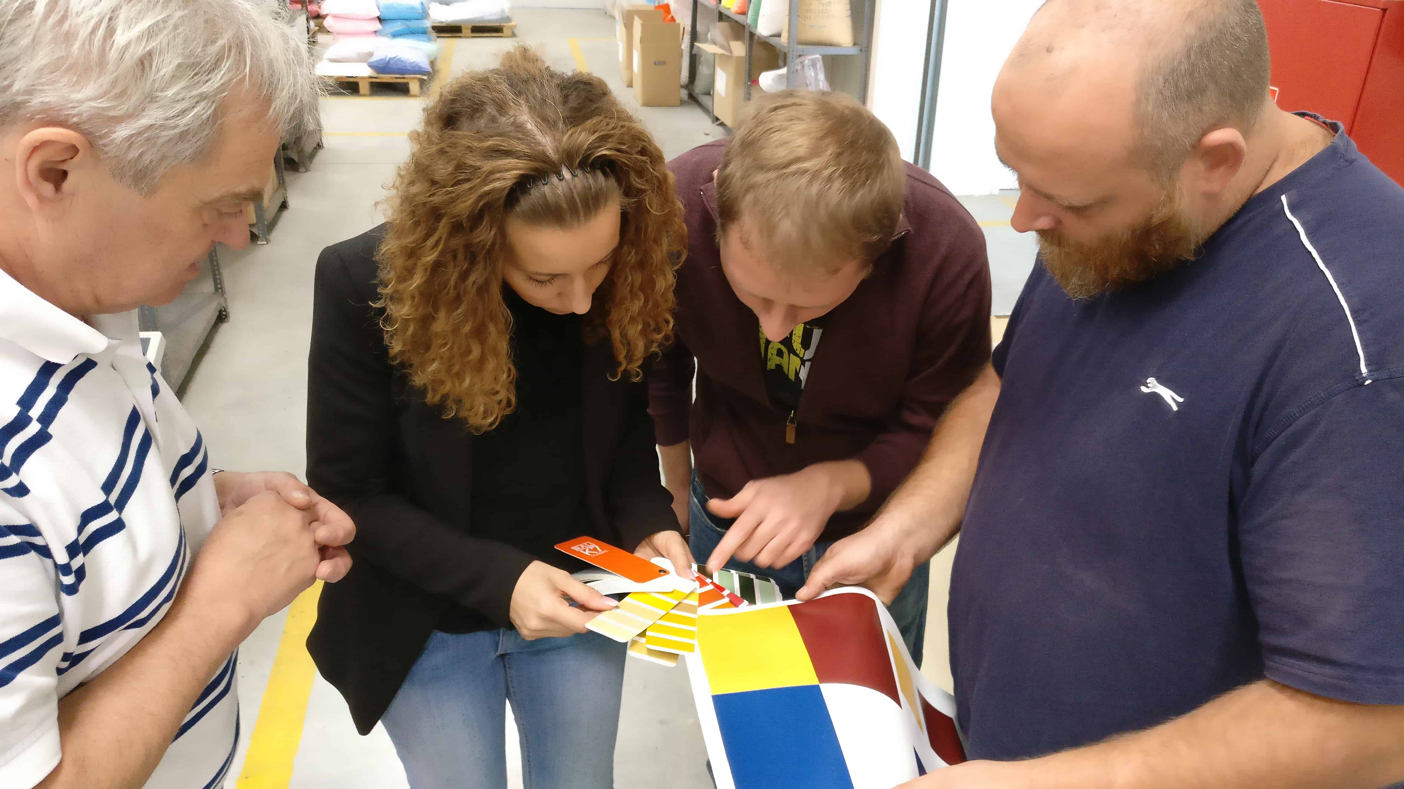
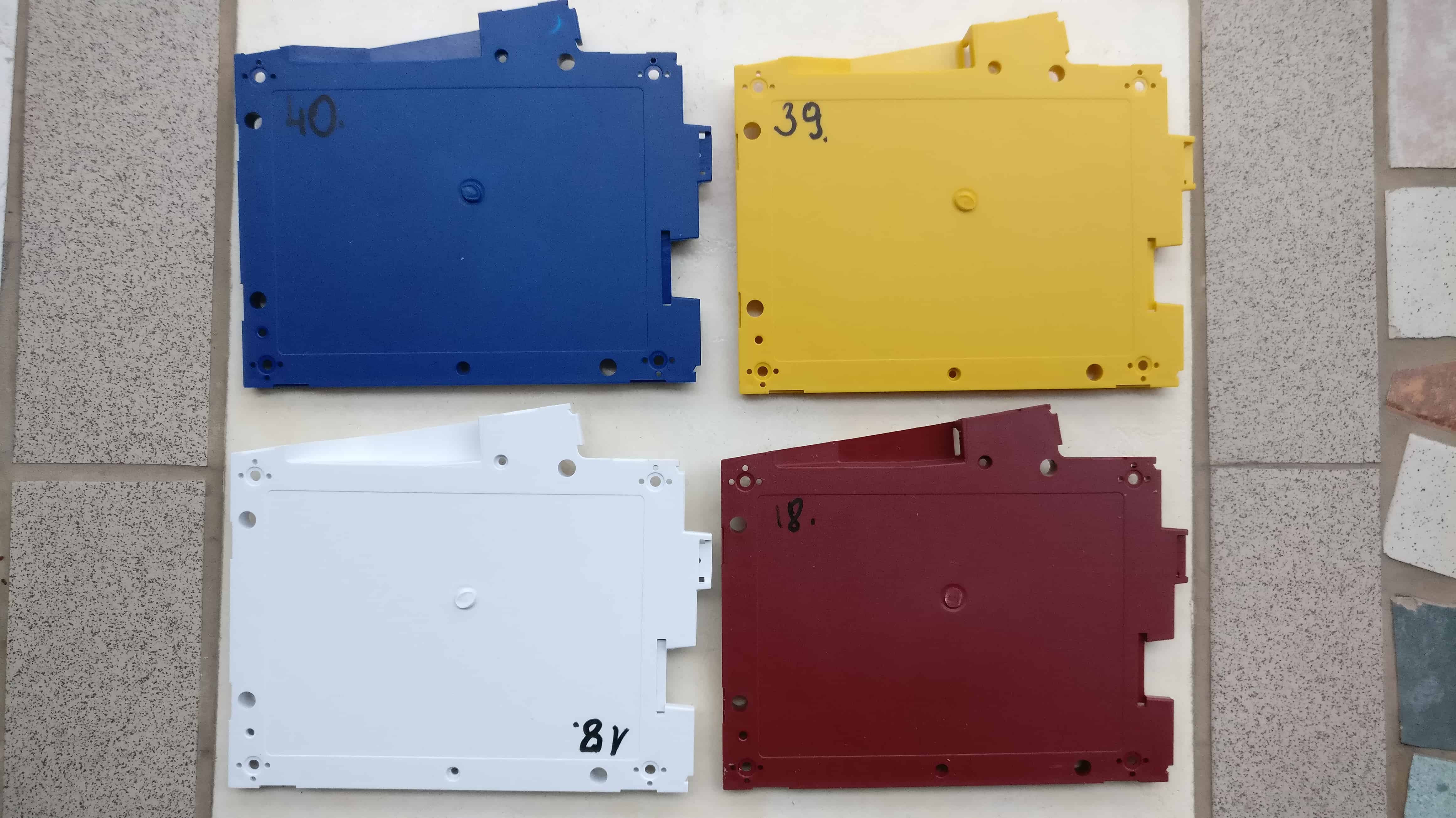
Colored cases
We recently visited a company to choose the colors of the non-black cases. Instead of using their stock colors, we ended up asking for custom colors according to the rendered images that you can see on the order page.
I’m happy to report that the first colored UHK cases just rolled off the assembly line.
We can’t wait to see the colored UHKs fully assembled!
Miscellaneous progress bits
The correct back stickers have finally arrived, and we applied them to the back of the cases. Next, the top and bottom cases are (separately) assembled featuring all the bells and whistles.
We recently noticed that the pad printing of the right case buttons is off. The position of the print has been misaligned by 2 mm. New case buttons will be printed this week.
We also noticed that the LED display was hard to see in bright light, so we asked our supplier for some new samples, and they were able to improve upon the design. Now the manufacturing of 3,000 new LED display films is in progress. They’ll likely arrive next week, at which point, we’ll remove the old films from the displays and apply the new ones.
The outer boxes into which the smaller product boxes will be packed for shipping are being manufactured and are scheduled to be ready next week.
I’ve been super busy with the firmware, landing about 150 commits in the firmware repo since our last update, and released a new version. You’re welcome to read the changelog.
Robi has finished the cross-platform build system of Agent and released versions for Linux, Mac, and Windows. The next step will be the the auto update feature, and integrating the firmware upgrade scripts to Agent, so Agent will be able to update the firmwares of the keyboard halves and modules.
As for the estimated delivery schedule, we plan to send out the 50 pilot run UHKs by the end of November. Then we’ll wait about a week or two for the feedback of the pilot run recipients to make sure that everything is up to snuff. Afterwards, we’ll try our best to launch the delivery of the remaining 1950 UHK of batch 1 in December, but due to holiday season we may have to postpone the shipments to January. We’re trying hard to deliver as soon as possible, but we won’t rush things at the expense of quality.
Thank you for reading this update! We’ll talk to you on 2017-12-14.
Hi there, and welcome to our monthly status update!
TL;DR: We’ve passed FCC certification, and CE is in progress. We’re progressing with assembly, loads of UHK boxes arrived from the printing factory, and the UHK accessory boxes are already packed. The firmware and Agent have matured substantially. We’re waiting for final answers from TÜV to proceed further.
We’re aiming to send out the pilot run UHKs in October, and start the delivery of the rest of the first batch of 2,000 UHKs in November. If you backed us after 2017-07-13 then you’re in the second batch, which is expected to ship in March 2018.
FFC and CE certification
A week ago, we got great news from TÜV:
“All FCC 15 ready and just PASS for Radiated Emission. Producing the report now.”
Then I asked about CE, and to my surprise they told me that they didn’t know that we also needed CE measurements. I searched my emails to see whether I miscommunicated something, but I didn’t. Not only did I mention both FCC and CE, it was part of the subject line. It’d have been hard to make this any clearer.
I told TÜV that we would really appreciate if they wrapped up CE as fast as possible, especially considering the recent delays that they added to our project. They promised me that we’ll have the official CE report by the 18th. They did not promise an ETA regarding the FCC report, but told me that it’ll be ready “soon”.
To be perfectly honest, given the recent complications, we’d like to switch to an alternative certification body, but it’s way too late, and we don’t have any other options in Hungary. Going forward, I’ll be pinging them regularly to try to keep this under control. I believe this will get sorted out soon, and we’ll receive the certification papers shortly.
Our contract manufacturer is eager to start production, and as soon as we receive the reports from TÜV, we’ll start the PCBA of the pilot run units.
Manufacturing progress
Even though the PCBs are not assembled yet, we’re working on assembling and packaging everything else.
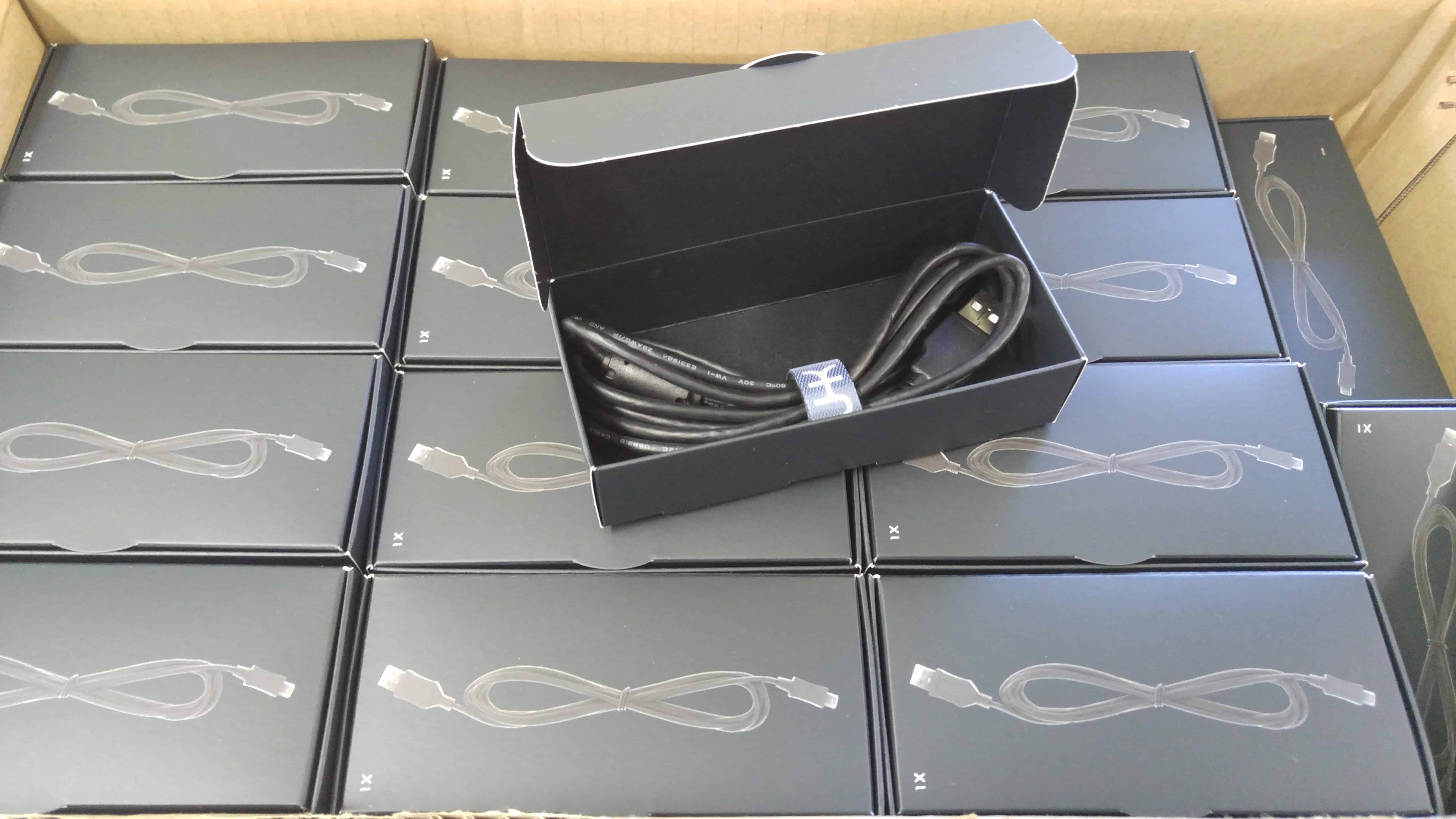
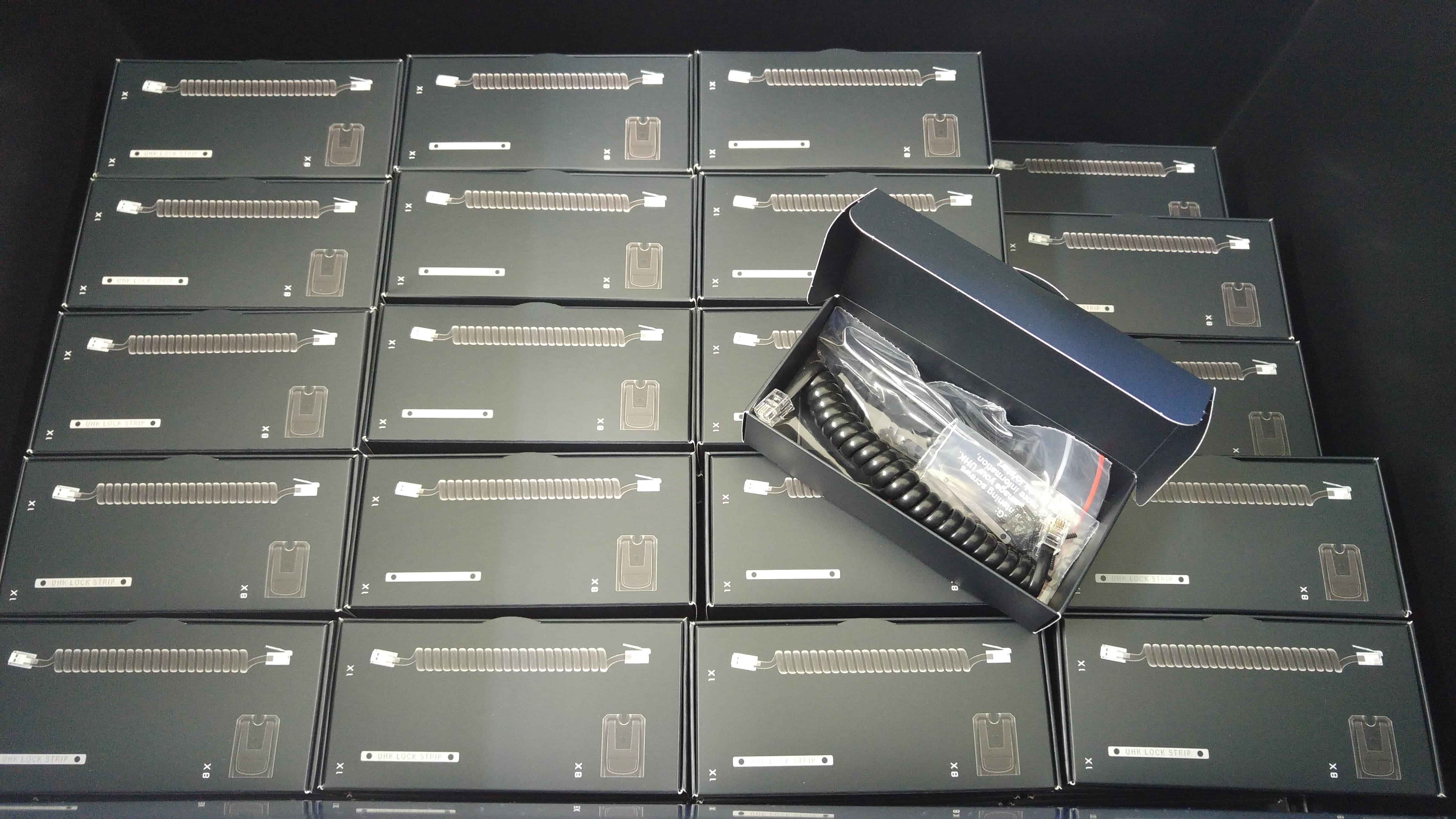
There are two small boxes inside of the main UHK box, one containing the USB cable, the other containing the bridge cable, the flip-out feet and their screws, and a lock strip that securely locks together the halves if you choose to use it. We’ve packed 500 of these boxes.
We’ve tested 500 USB cables and 500 bridge cables, and they all worked flawlessly. This is a good sign. Our cable suppliers definitely seem to be on par.
Right now, the case buttons are being pad printed. These are the first samples:
We’ve chosen the top, brighter color sample, even though the difference is hardly noticeable in this picture. Unlike our first pad printing supplier candidate, this supplier seems to perform just as expected. The prints are razor sharp, spotless, precisely positioned, and the correct font is used.
The cases are semi-assembled and we’re waiting for the back stickers to proceed further. We already received 3,000 stickers from the printing factory, but they were shiny instead of matte. Then we received a supposedly corrected batch of 3,000 that were matte, but lacked anti-scratch coating.
Now the printing factory will print yet another 3,000, and we’re hopeful that they’ll get it right this time. This journey is as expensive for them as it is time consuming for us. Once we get the correct back stickers, we’ll apply them to the case, and then glue small rubber feet to the cases,concluding their assembly.
We’re also making progress with the colored cases. This is the first colored case sample of a random test color:
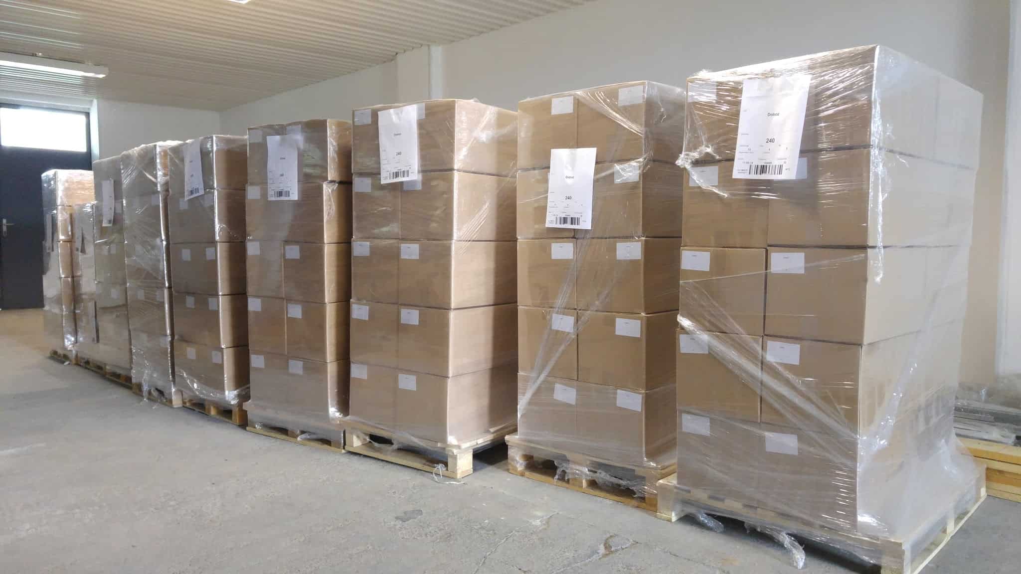
Last but not least, 3,000 UHK boxes have arrived from the printing factory:
Being pre-assembled boxes, they take up quite a lot of floor space. 15 pallets to be exact. Maybe we shouldn't go with preassembled boxes next time.
Firmware progress
I’ve been heavily focusing on the firmware during the last couple of weeks and managed to make quite a lot of progress.
More than anything else, I wanted to make the I2C communication between the keyboard halves rock stable. Placing the bypass capacitors as closely to the IS31FL3731 LED driver ICs as possible made the communication much more robust, but from time to time it halted. The capacitors couldn’t totally negate the parasitic capacitance of the I2C bus, and these LED drivers being as picky as they are, the problem persisted.
Eventually, I managed to find a solution that is described in the AN-686 application note. The core problem is that when I2C communication halts in the midst of the communication, it makes the state machine of the slave that is being addressed wait for further data. Just as suggested by the application note, I clocked through the slave by toggling SCL until SCA went high.
This helped tremendously, and it made communication always recover when disconnecting and reconnecting the keyboard halves, but when using the keyboard over an extended period, the left half eventually became non-responsive.
I could reproduce this issue fairly reliably by making the right keyboard half reenumerate as the bootloader. This interrupted the communication with the left keyboard half, but didn’t unpower it, which always happens when disconnecting it. I also figured that the left KL03 MCU is the culprit because when I rebooted it, the communication always resumed. I needed to fix this issue.
First try: I2C watchdog
I thought that the issue could be solved by implementing an I2C watchdog not only for the right keyboard half but also for the left keyboard half. This proved to be a lot more difficult than anticipated thanks to a bug that I made earlier.
I created a timer interrupt, and put the I2C recovery code into it to reinitialize the I2C driver. Among other things, it called the Init_I2C() function. I realized that when commenting out Init_I2C() within the timer interrupt, the firmware worked, but when uncommenting it, it hit a hard fault. This was seemingly impossible because the hard fault also got hit when I deactivated the timer interrupt, so Init_I2C() wasn’t ever called within it.
I couldn’t figure this out, so I managed to summon Santiago who delved very deep into the issue. It also turned out that the debug version didn’t work at all, so he had to figure this out by looking the disassembled, gcc-optimized ARM assembly code of the firmware.
Santiago finally concluded that the issue was that I defined the I2C_Handler struct within a function so the struct got allocated in the stack, but after returning from the function this variable got deallocated. The problem is, the KSDK still tried to use the struct even after being deallocated, which triggered a hard fault.
The issue didn’t surface when referencing Init_I2C() once across the codebase because the function that contained the definition of the I2C_Handler struct got inlined so it was like being defined in main(), and never got deallocated. But when referring Init_I2C() twice, it wasn’t inlined anymore and the issue surfaced.
After this incident, I’ll surely think twice about making KSDK variables global. For even more details, Santiago created a slide which you’re welcome to study.
Unfortunately, even though my left-side I2C watchdog was running, it still didn’t do the trick. Somehow, communication didn’t recover. Which brings me to my second try.
Second try: hacking the KSDK
At this point, it was down to debugging. I needed to see not only what went over the wire between the MCUs of the left and right halves, but also what was happening inside of the KL03, especially regarding the state of its I2C driver. Using the debug feature of Kinetis Design Studio didn’t work for me as it pauses execution and given the realtime nature of the communication, it doesn’t behave as expected.
Then I tried to make semihosting work which basically allows the microcontroller to dump strings via the debug probe to the console using printf(). Unfortunately, I couldn’t make semihosting work because it crashed the microcontroller for some reason that I couldn’t figure out. Semihosting would also have posed a significant runtime overhead anyways, and it might have made the firmware behave differently, so maybe it’s not a big loss. In any case, I had to find an alternative solution.
Finally, I figured that I’d just use a spare peripheral of the microcontroller to dump relevant data, and I ended up using the SPI peripheral of the KL03. For this, I needed to temporarily repurpose two GPIO pins that were used to scan a row and column of the keyboard matrix. This made the prototype practically useless for touch typing temporarily, but that’s a small price to pay.
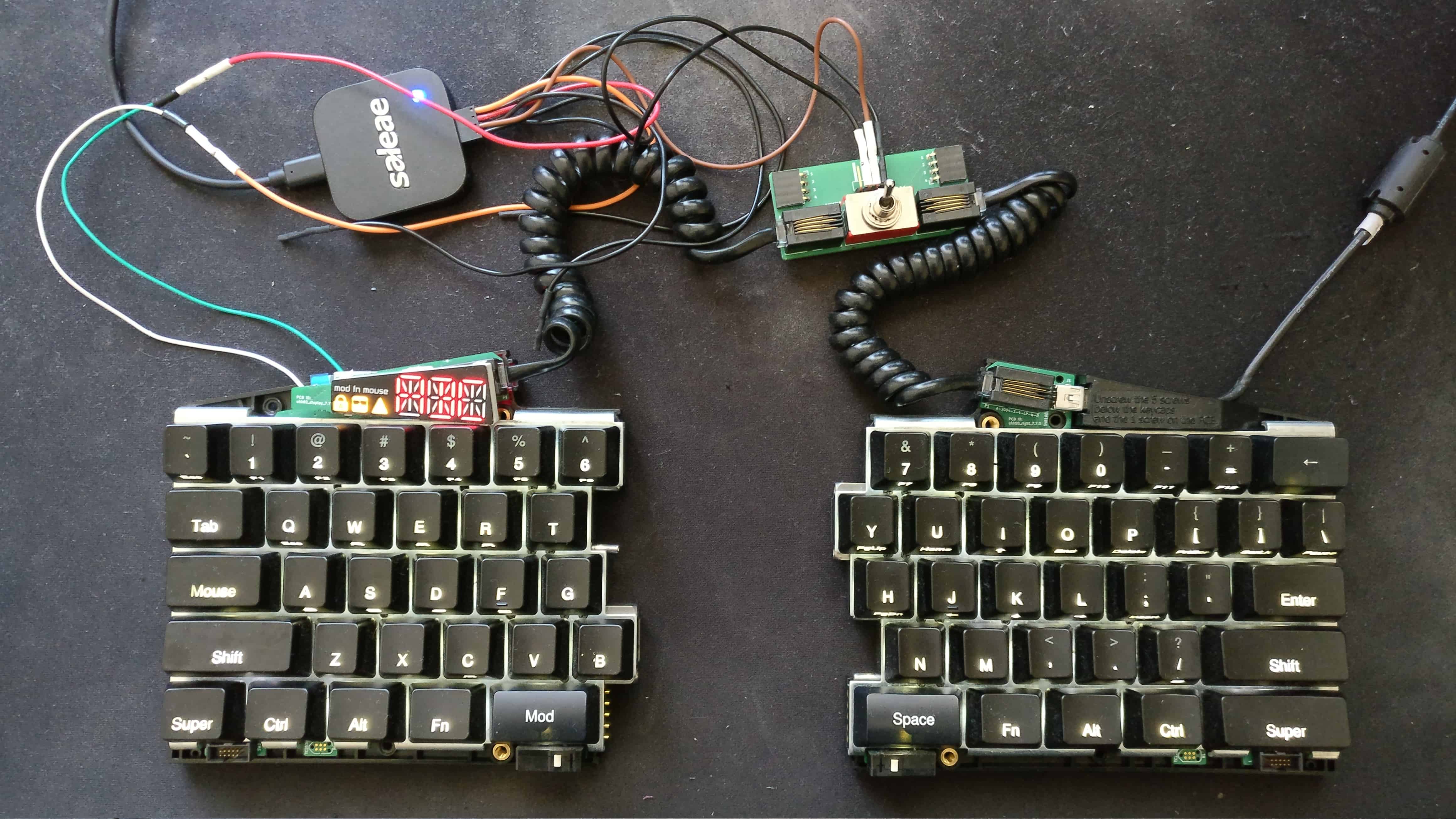
At this point, my prototype looked like this:
The halves are interconnected by two spiral cables via an adapter board. The adapter board features a 4P2T switch which allows me to disconnect and reconnect the halves easily for testing purposes. The adapter board also breaks out the wires of the cables. The wires I’m interested in are the SDA and SCL - the clock and data lines of the main I2C bus of the UHK.
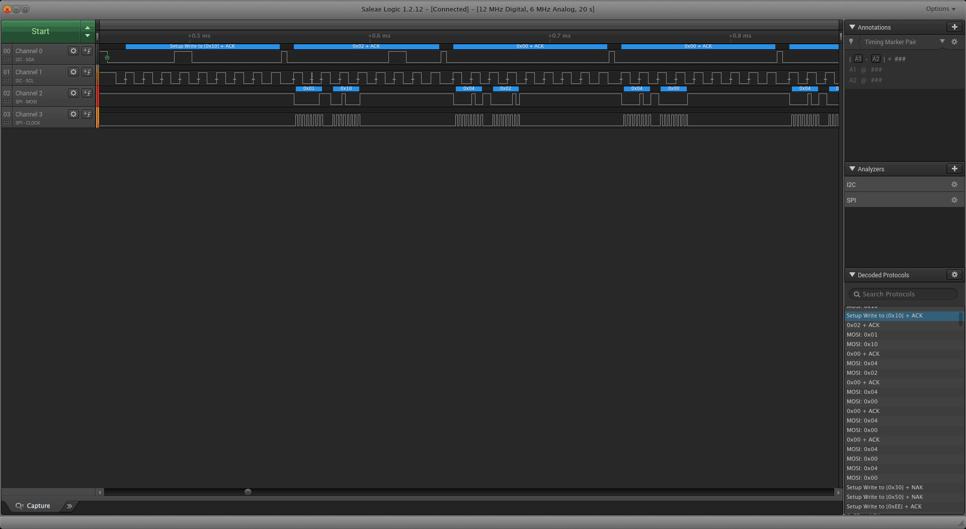
Apart from I2C, I also soldered two wires to the MOSI and SCK pins of the SPI peripheral. And finally, I connected the two I2C wires and two SPI wires to my Logic 4 analyzer.
What you can see above is the result of the fixed code. Channels 0 and 1 are the SDA and SCL of the I2C. Channels 2 and 3 are the MOSI and SCK of the SPI. For every byte sent by the master over I2C, the status byte and the received byte get dumped over SPI on the slave. The received byte correctly gets dumped over SPI right after receiving it, which is the way it should be.
The core issue was that the KSDK I2C driver is designed for fixed-size messages, but the UHK messages are variable-sized. They contain a header of a byte length, and a 2 byte CRC16-CCITT checksum. I ended up hacking the KSDK of both the left and right keyboard half to make it deal with our variable-length messages.
The effort that went into making the keyboard halves and the modules communicate reliably is quite incredible. It makes me appreciate already established and widely implemented protocols like TCP/IP that just work. I’m so happy that this critical foundation is in place.
Robi has been really pushing hard recently. I’m impressed by his work, and his efforts came to fruition as Agent is now able to read and write the configuration of the UHK. It’s a wonderful feeling to plug in the UHK, see the configuration appear on the screen, reconfigure it, and merely click a button to save the new configuration to the keyboard.
The smoothness of the user experience resembles the configuration applications of the largest keyboard manufacturers, but all things considered, Agent offers much more sophisticated configuration options than those keyboards.
It’s been a long journey to get there. And wouldn’t it be cool to visualize the development of Agent over its lifetime? As a matter of fact, it’s very much possible with Gource, so let’s take a look at it:
While we’re at it, let’s also take a look at the firmware repo:
There’s still a lot to do, but given the current state of the firmware and Agent, even the pilot run recipients should experience a smooth ride.
Thanks so much for your support!
In our previous update, I elaborated in detail on the manufacturing challenges which have been causing us delays. After publishing our update, it felt awesome that so many of you got in touch with us and expressed your fullest support. We’re glad that you share our pursuit for quality, understand the nature of the delays, and agree that the UHK is worth the wait.
What has been said about the challenges of manufacturing clearly reverberate in this update. After all, who would think that it’s possible to mess up mere stickers (twice), or misunderstand clearly written, basic instructions about the certification process. But it’s the real world, and human errors do happen.
PCB assembly should happen shortly, just after we get the FCC and CE reports from TÜV. Then we’ll quickly assemble the pilot run units and send them out, and the rest of the first batch will follow. We can’t see any major challenges ahead us, we just have to wait longer than anticipated which is something none of us like, but it’s seems that it’s the nature of the hardware business.
Thanks again for your support and understanding! Let’s keep in touch, and we’re excited to talk to you on 2017-11-16.
Hi there, and welcome to our monthly status update!
TL;DR: All of the keyboard molds are finalized, and the plastic parts for the pilot run are ready. The PCBs of the pilot run are also ready, and waiting to be assembled. We’re waiting for TÜV to certify our design, and then the PCBs will get assembled. The printing factory is nearly ready with the UHK and palm rest boxes. We need about one and half month to start delivering batch 1. Please see the end of this update starting from the “The state of the pilot run” section to see why.
You can always check out the expected delivery date and update your shipping address on your Crowd Supply account page.
Mechanical parts
We’ve been tweaking the molds for seemingly forever. This process is usually extremely time-consuming and involves numerous iterations, especially for high quality plastic parts like the cases of the UHK. Thankfully, we’ve arrived at the end of this journey by manufacturing the top case parts, which were the only missing parts.
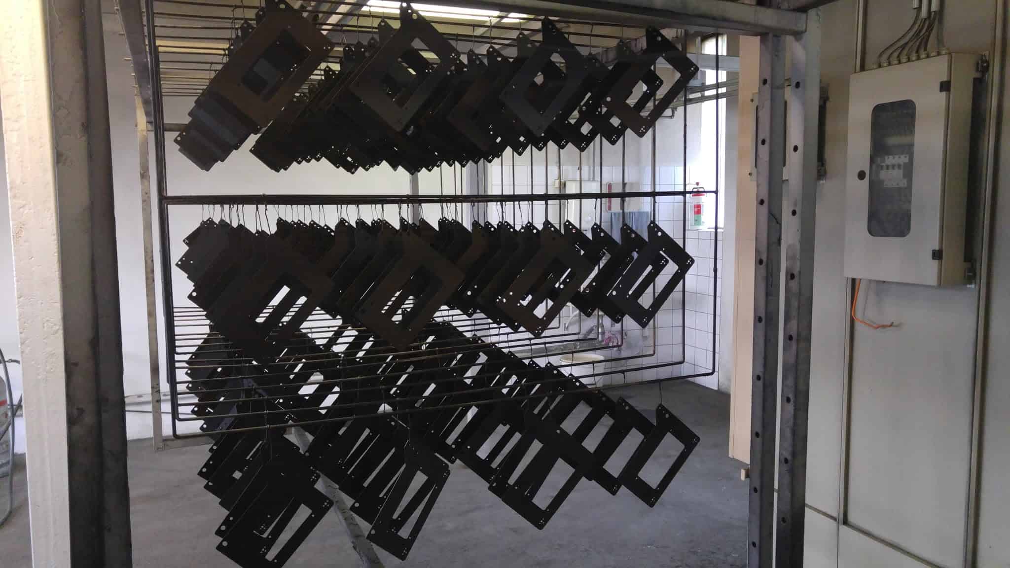
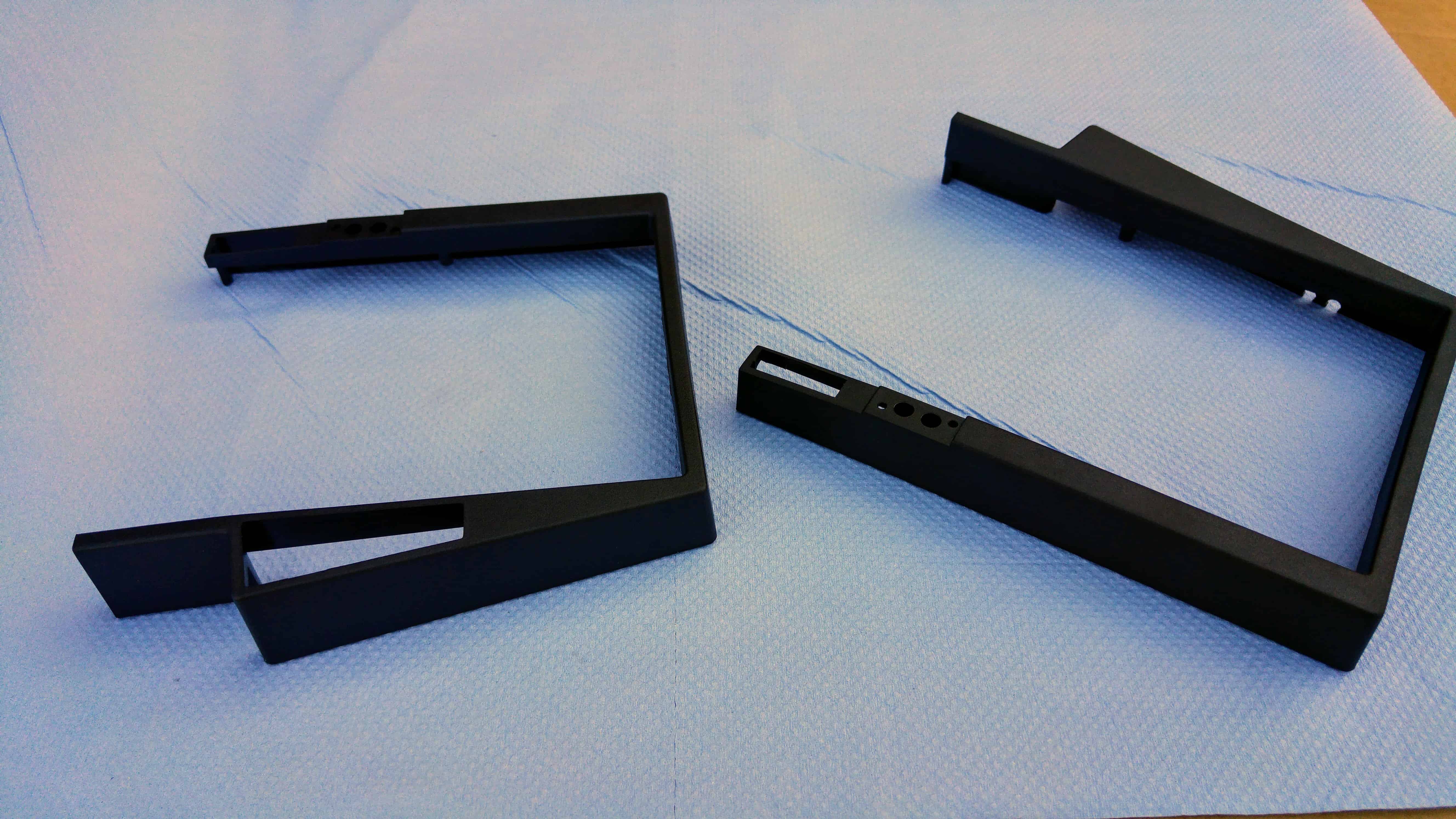
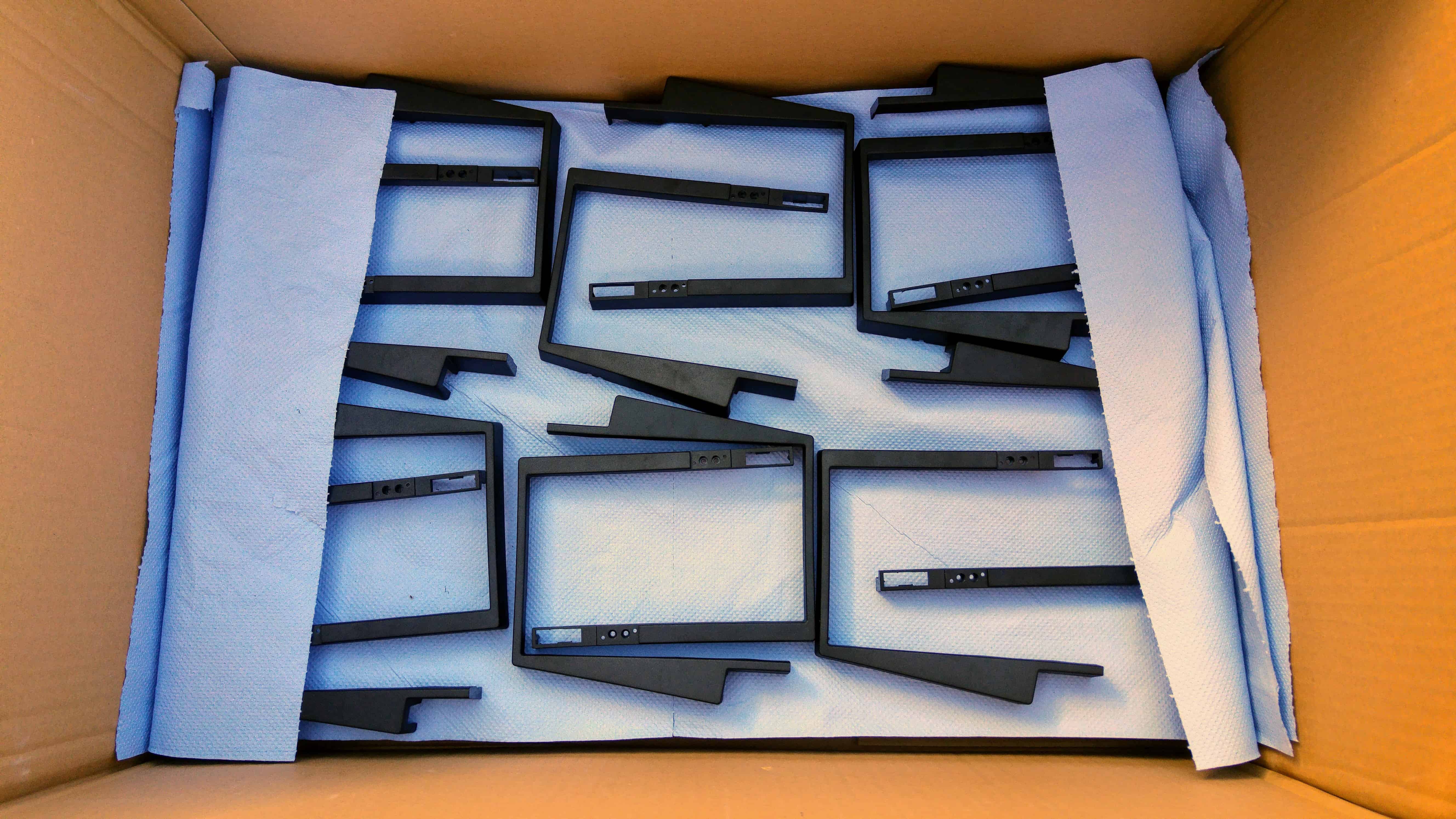
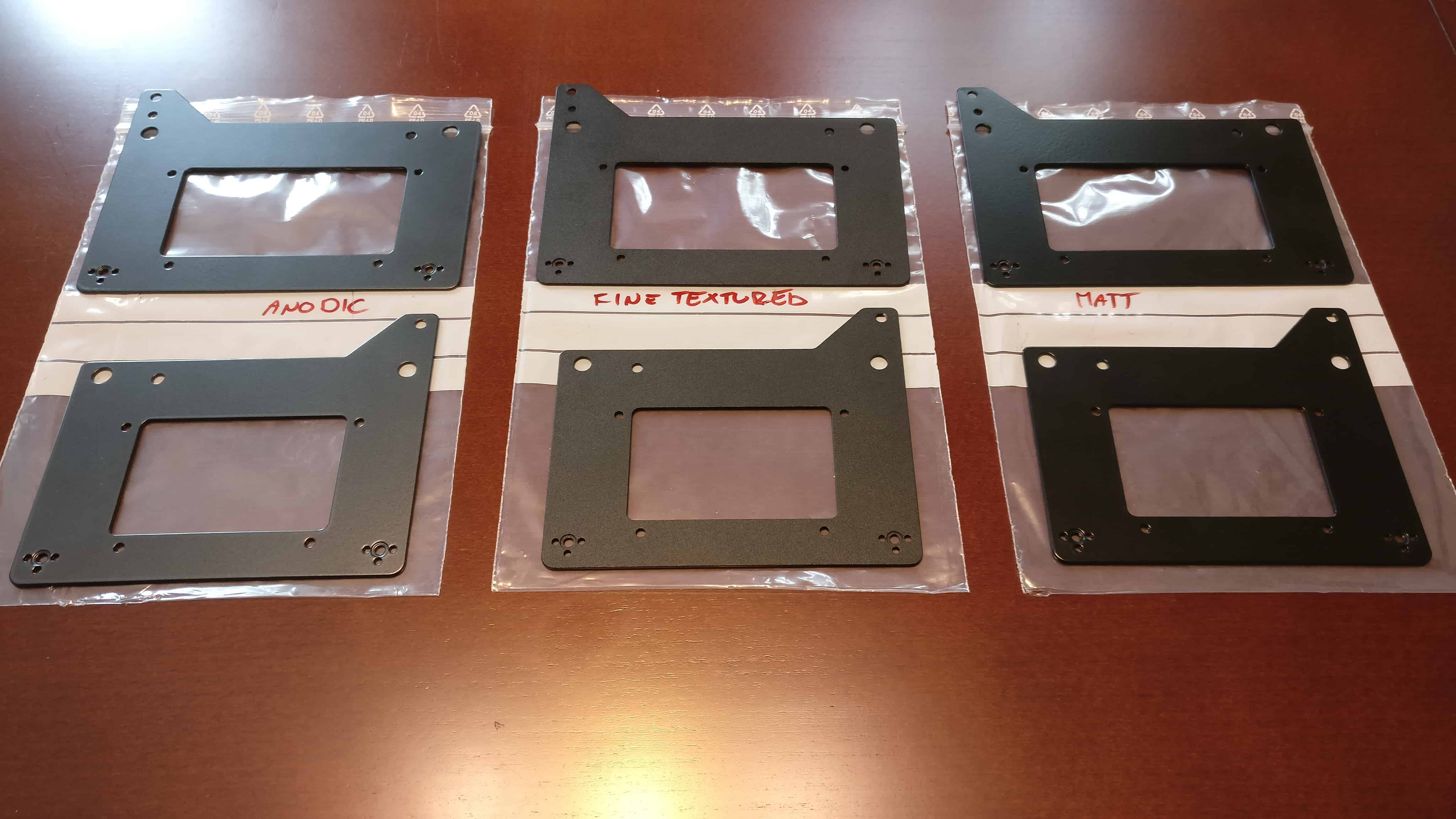
Of all the mechanical parts, only the baseplates of the palm rest are left undone. We weren’t completely satisfied with the coating of the latest samples we got, so we asked for new ones featuring three different kinds of powder coating.
We agreed that the middle, fine textured sample is the one to go with, as it most closely resembles the texture of the UHK case. The base plates of the pilot run are being laser-cut and they’ll be powder coated in a couple of days.
These plates will conclude the manufacturing of every mechanical part. Finding all the suppliers of the mechanical parts, and coordinating the manufacturing process has been an enormous undertaking for us as a small company, and we’re delighted to see that it’s coming to an end.
Pilot run PCBs
The 50 PCBs of the pilot run are ready, and waiting to be assembled.
UHK panel, top sideUHK panel, bottom side
Board assembly will start as soon as we receive the FCC and CE certifications from TÜV. Actually, the UHK may already be certified, we just haven’t heard of it because our contact person at TÜV recently quit. Now his boss is our new contact who is very busy, but nevertheless, he promised to get in touch with TÜV Netherlands and sort things out by the end of the week.
Printing the boxes
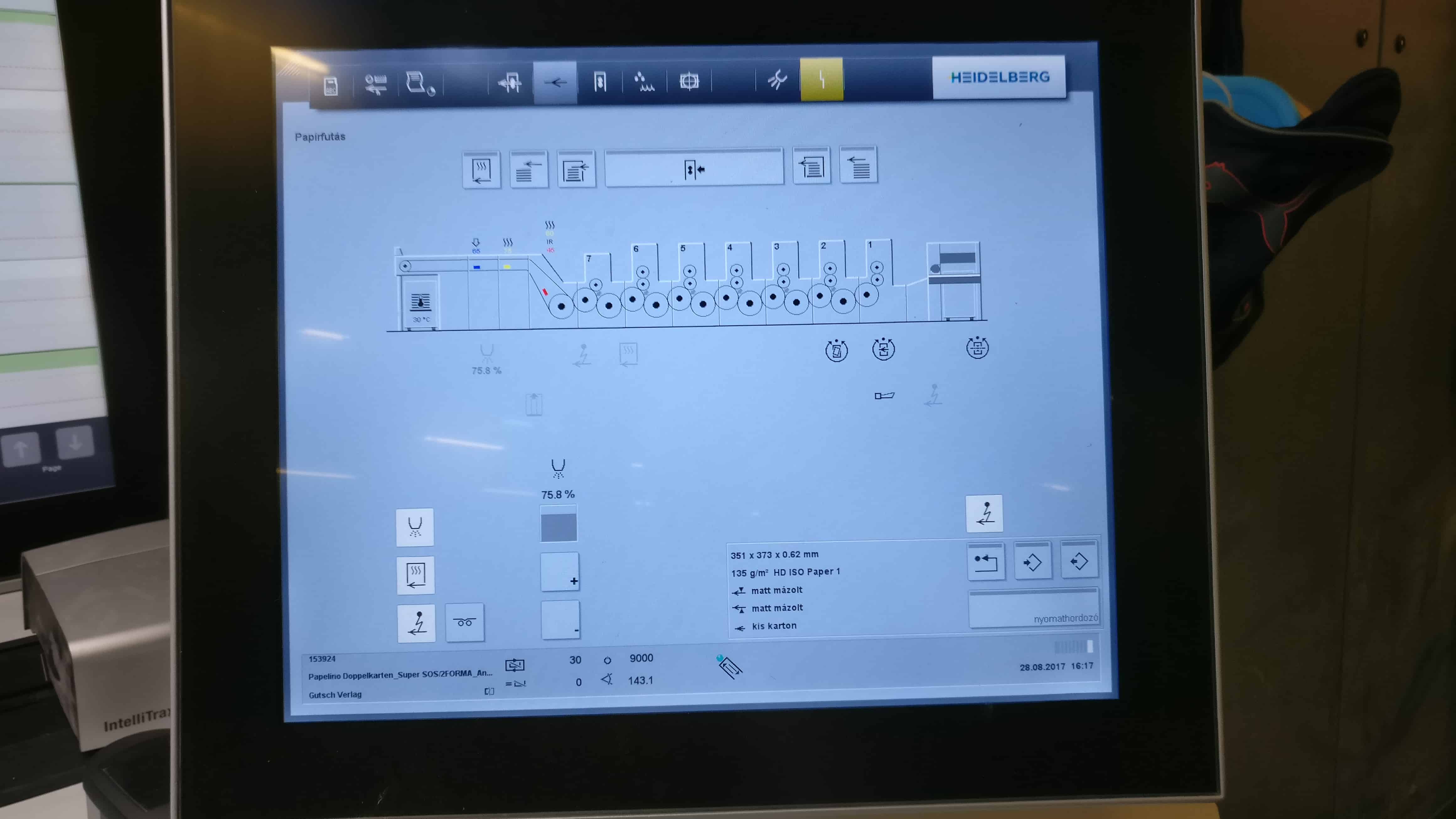
We’ve been in the printing factory lately, watching as the sheets of the UHK packaging as they get printed. I didn’t expect anything fancy and boy, was I wrong! The Heilderberg Printmaster printing press which was used to print the UHK packaging is a monumental machine and it was quite a sight.
The inside of the beast shown on its control panel
Packaging is not the meat of the product, but we do believe that it creates an impact, and we don’t like to leave any stone unturned, so we’ve put quite an effort into designing it. Hopefully it’ll show when you unbox your UHK and palm rest.
The state of the pilot run
We’re very close to assembling the pilot run PCBs, and sent out the pilot run surveys to the 50 participants recently.
Outstanding issues:
As mentioned above, we’re waiting for TÜV. As soon as the UHK PCBs get certified, we’ll commence their assembly. This can happen in days.
Also mentioned above, the base plates of the palm rests are being manufactured and then powder coated. These should be ready in a week.
We’re waiting for the UHK boxes, the palm rest boxes, and the back stickers of the UHKs. The printing factory should send the goods to us in about a week.
The case buttons of the UHKs have to be pad printed. We’ve received a couple of samples from a Hungarian company that had numerous issues. We found another, nearby company who will likely get the job done well and quickly, possibly in a week.
Once the above issues are resolved, assembling the pilot run UHKs will happen in a matter of days, and production speed will ramp up rapidly as we gain more experience regarding the assembly process.
The remaining 1,950 UHKs of batch 1 will follow quickly after receiving some feedback from pilot run recipients.
Given that the pilot run has yet to be sent out, then we have to gather some feedback from the pilot run recipients, and then assemble the next batch of PCBs, we have to push the current delivery date by one and half months, at which point the delivery of the remaining items of batch 1 should start. This brings me to the following point...
Some words about delays
Some of you are growing impatient due to the number of delays that have been introduced over the lifetime of the project. This is understandable, and we couldn’t be more eager to ship sooner. I’d like to elaborate a bit on why it’s taking so long to deliver.
You could see several bullet points in the above section, each involving at least one supplier of ours. We have dozens of such suppliers all around the world (mostly in Hungary, and some in Serbia, China, and Taiwan), and each of them was chosen from numerous suppliers.
For example, I contacted about 30 suppliers for the LED display alone, then chose one, and then exchanged about 200-300 emails with them, got a couple of samples, dealt with customs quite a bit, and all this resulted in the current LED display. And this is a single supplier!
András and I are running this show, two guys from Hungary. I work more than 300 hours a month solely on the UHK, and András is doing his fair share too. The only reason we don’t work more is because we can’t without flat-out burning out. We could add more workforce and experts to the project, resulting in faster progress, but they’d cost a lot of money and we have no room financially as custom tooling and starting and maintaining a supply chain and manufacturing capability is awfully expensive.
Speaking of finances, we’re extremely conservative. Full disclosure: I earn $2 per hour, and András earns $0 while working on the UHK mostly and in his own company part time. The vast majority of the money we spend is on manufacturing and R&D. We realize it’s your money and trust that you gave us to make this project a reality and we’re doing everything within our power to make this a success.
We could simply go to an OEM in China or Taiwan and use their resources to fix many of the issues we’ve encountered, but we’ve made a conscious decision to manufacture the UHK in our home country. The reason being that this way we can directly oversee manufacturing and QA without camping all the time in Shenzhen, and we can be more nimble in the long run, after going through the initial formidable hurdles of starting up all this.
I should also add that the UHK is not exactly an average keyboard, and not just a split keyboard, but a split, modular keyboard that is extendable with modules, which is something that, according to my knowledge, nobody has ever done before. The overall complexity of the project is quite staggering from a mechanical, firmware, electronics, and software standpoint compared to an average keyboard. In a couple of aspects, it’s the most complex keyboard ever made.
It’s also worth mentioning that we’re unwilling to make quality compromises, which also adds to the delays. Among many things, this has made the molds especially time consuming to make and refine.
When we announce a delay, it’s not because we were intentionally keeping quiet about it previously. It’s rather because of some unforeseen issue, like a critical supplier underperforming, a design issue that we couldn’t foresee, a supply chain issue, or virtually anything else we couldn’t think of previously. Very often we have to deal with these as we encounter them, and we always try to do our best. The road will eventually smooth out, but only after hitting every bump imaginable.
So, this is the long and the short of the situation. We’re really pushing it hard guys, and want to make this the best keyboard humanly possible. Let’s get there together, even if it takes longer than anticipated!
Thank you for reading this update! As always, we’ll be keeping you updated on a monthly basis via our blog and newsletter.
Hi there, and welcome to our monthly status update!
TL;DR: We’ve been making good progress towards mass production. The corrected prototype PCBs have been manufactured, tested, and sent to TÜV Netherlands for final certification. The PCBs for the pilot run are being manufactured. The configuration parser of the firmware has been fully implemented. BusPal got fixed, allowing us to update the firmwares of both keyboard halves. We’ll close the order cancellation period for batch 1 in a week.
You can always check out the expected delivery date and update your shipping address on your Crowd Supply account page.
Closing order cancellation for batch 1
Order cancellation for batch 1 will be closed in a week. You’re likely to be in batch 1 if your order was made on or before 2017-07-12. The reason is that we’ve already summarized the orders of batch 1, and we’re assembling these orders according to that plan. It’d cause a lot of potential problems to update the orders in the middle of assembly, and the best solution forward is to disallow order cancellation. You can cancel your order until 2017-08-24 but not afterwards. Thank you for understanding!
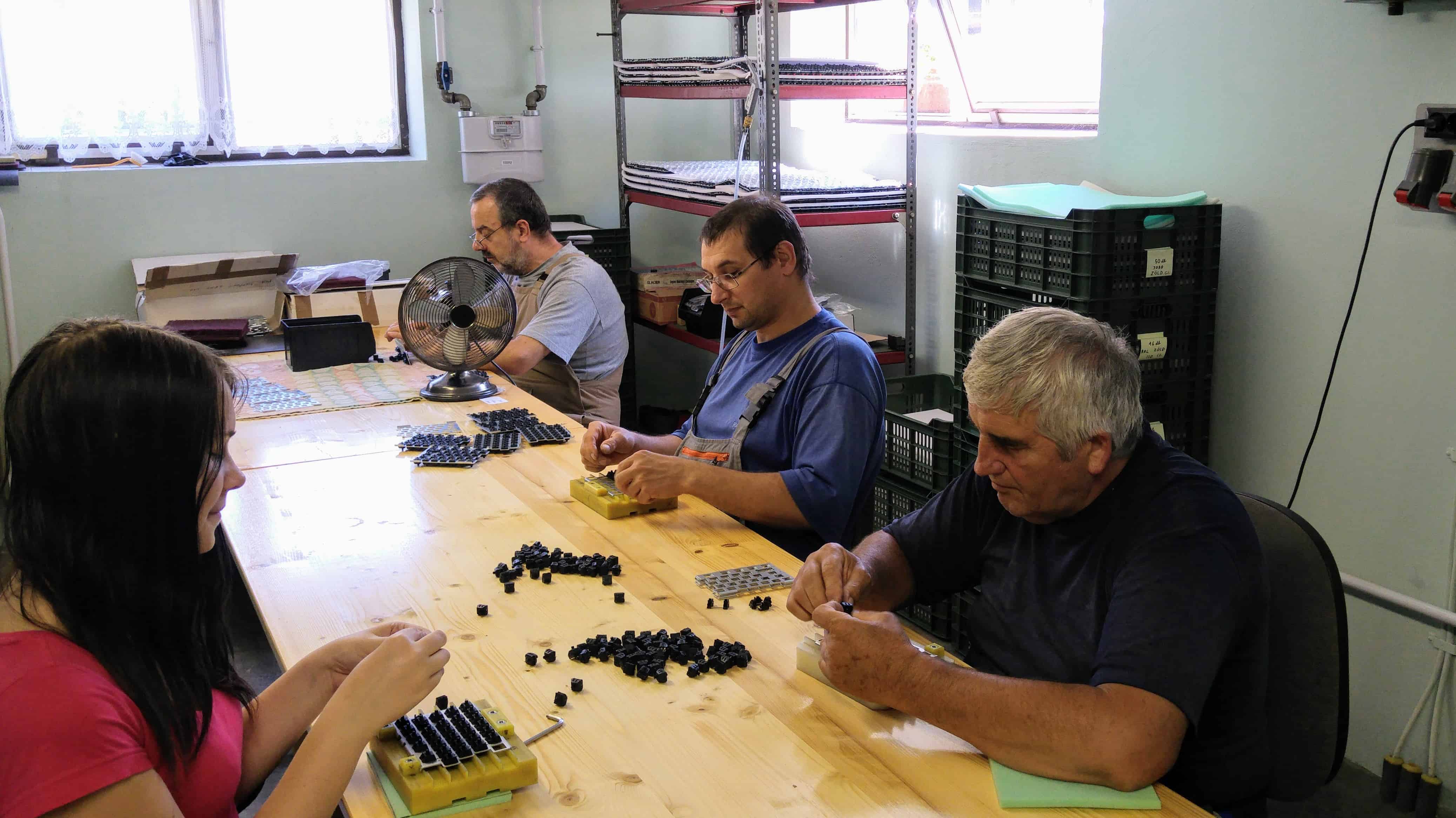
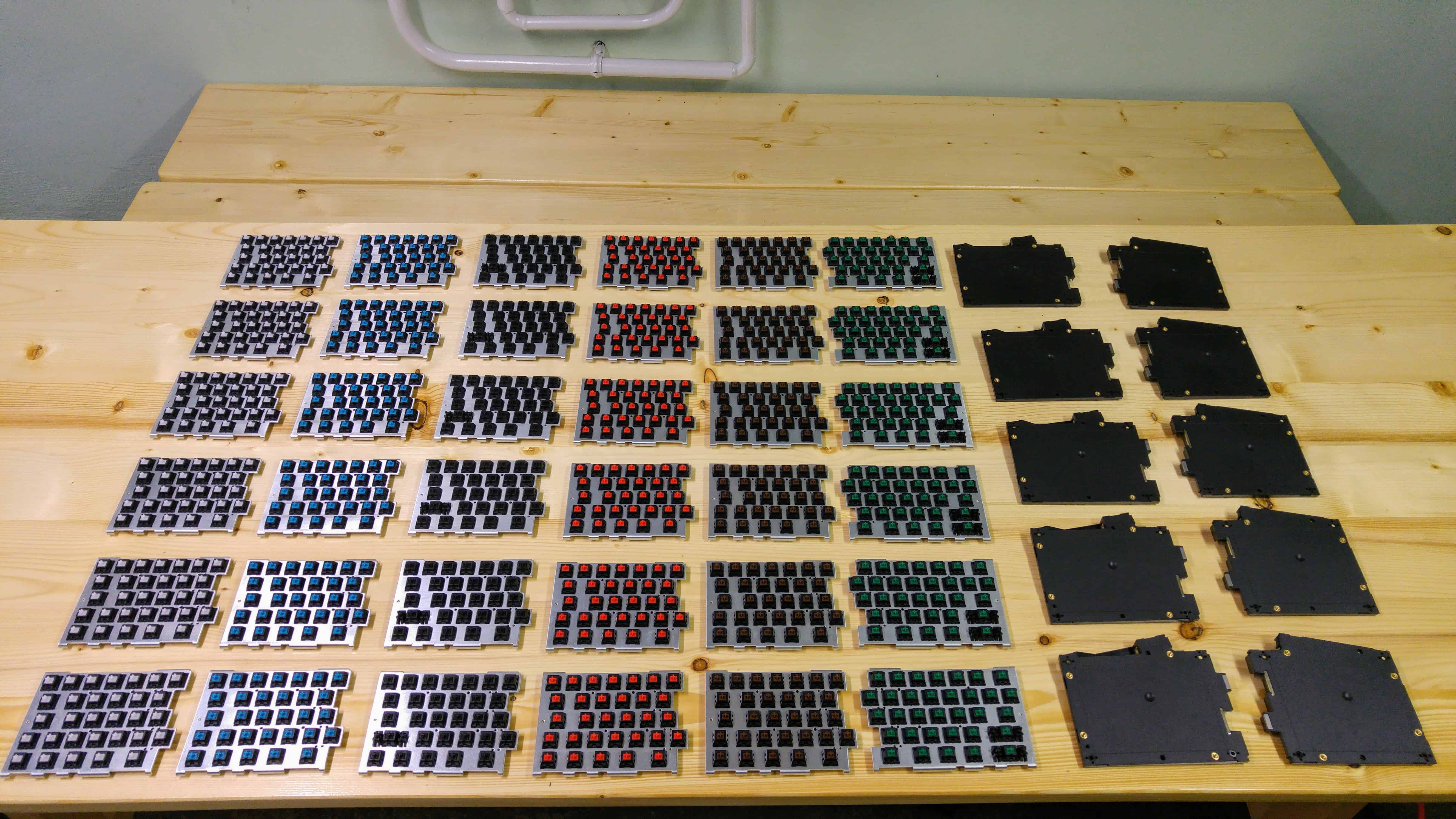
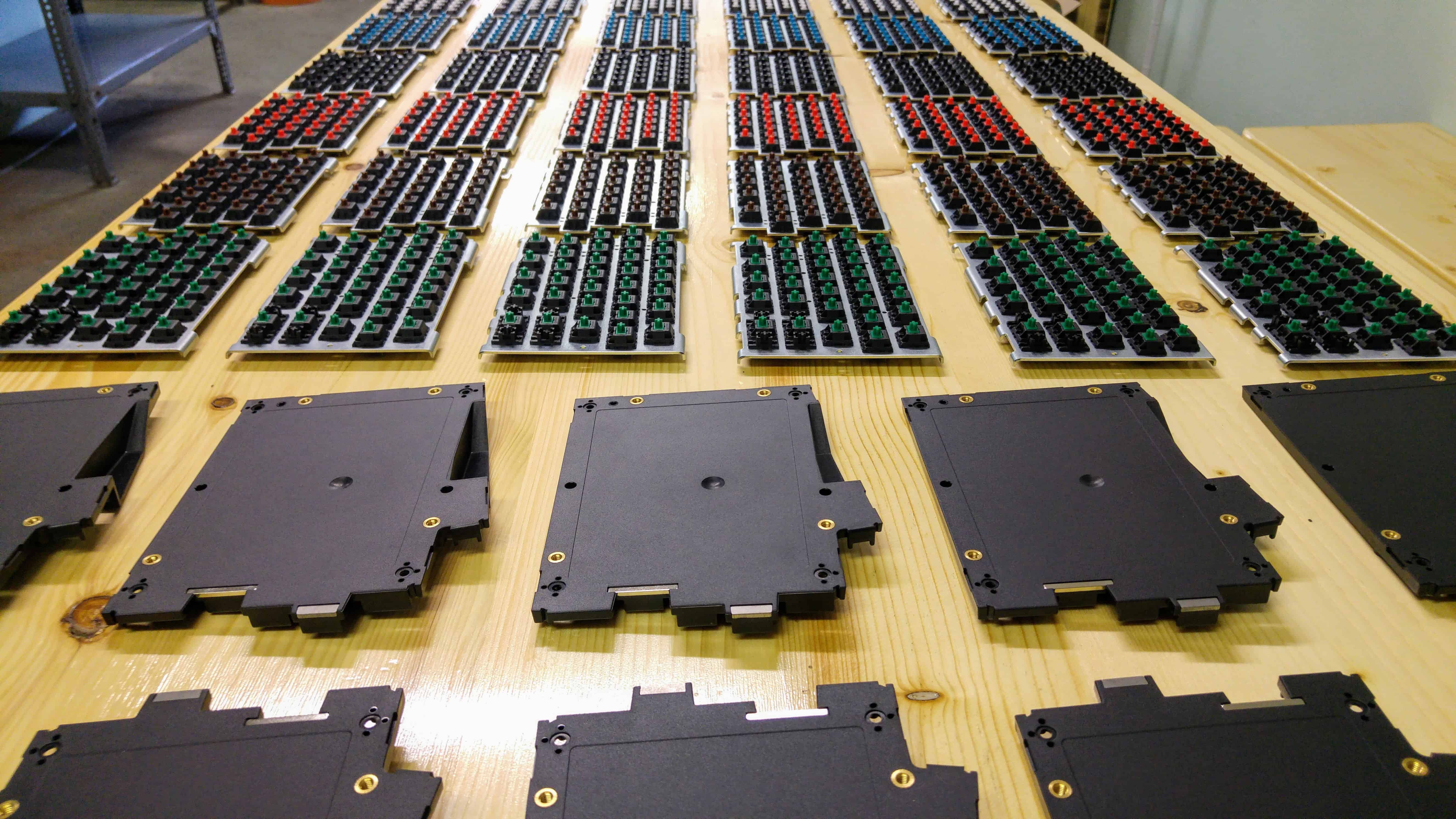
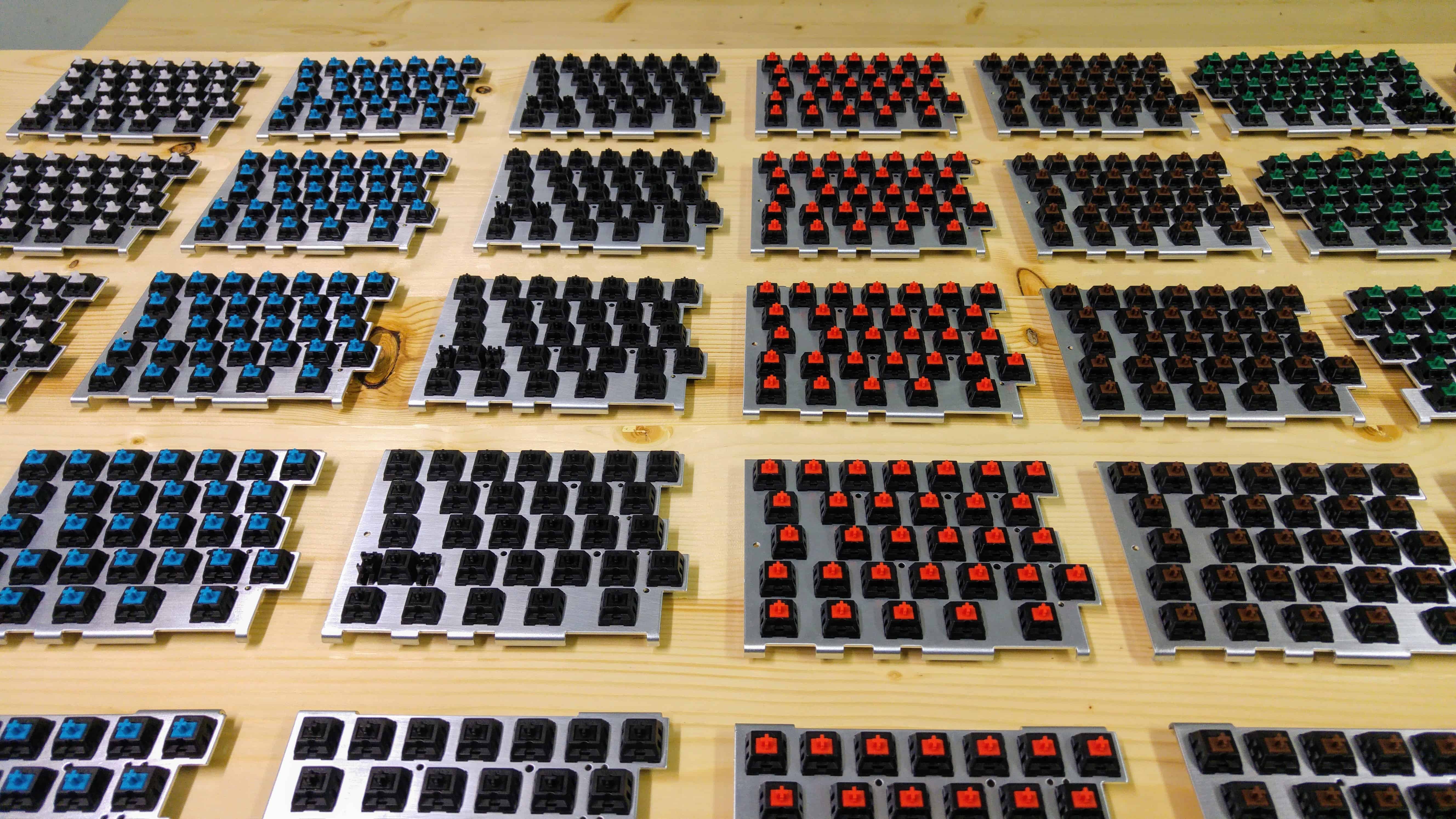
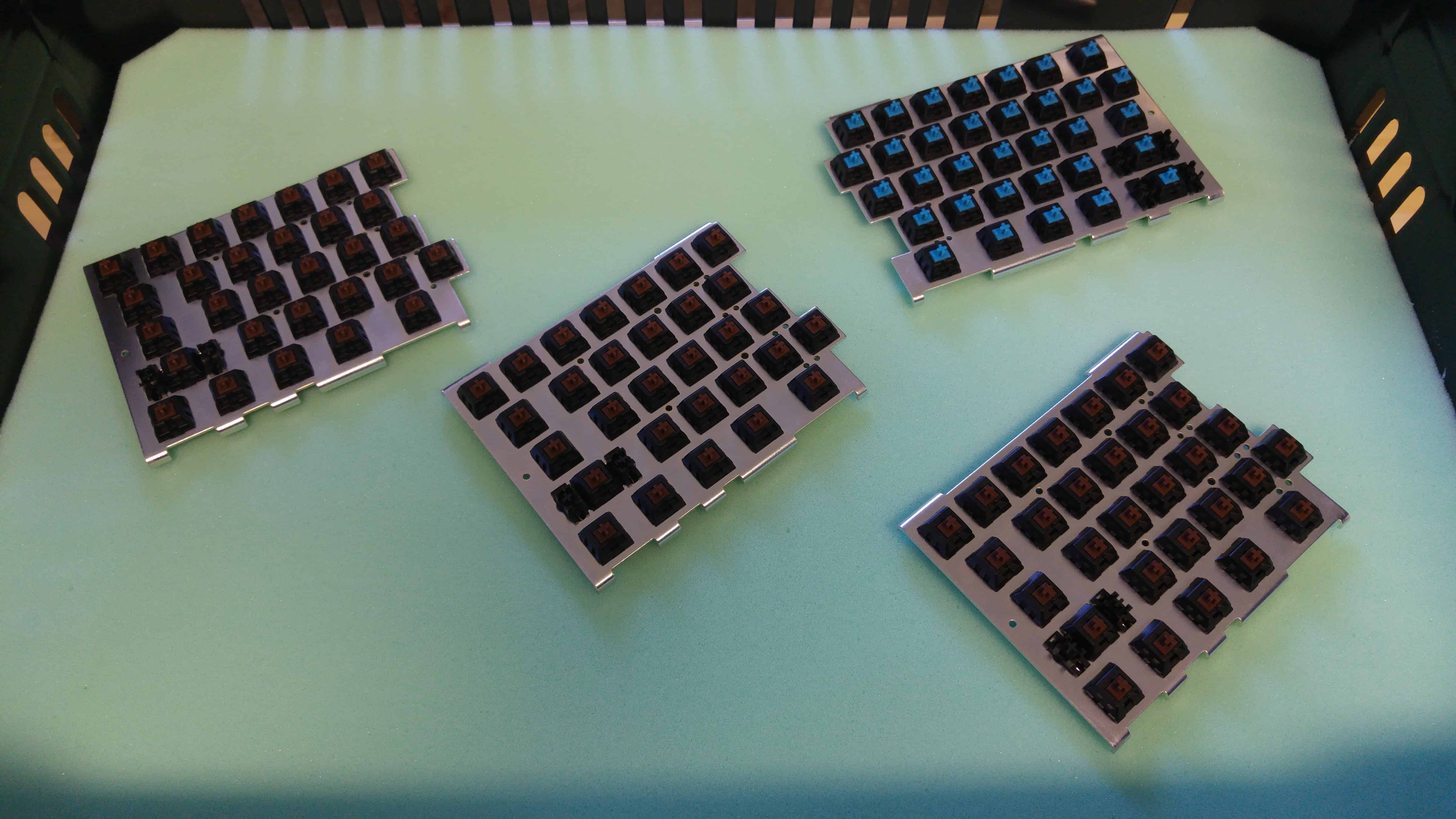
Assembling the plates and switches
Our team is working to assemble the 2,000 UHKs of the first batch. Right now, they’re busy with putting switches into the plates. So far, 1,000 pairs of plates have been assembled.
They’ve also half-assembled 150 pair of cases including the magnets, magnet-counter parts, and inserts, and excluding the small rubber feet and the back stickers. It’s a joy to see the fruits of their labor.
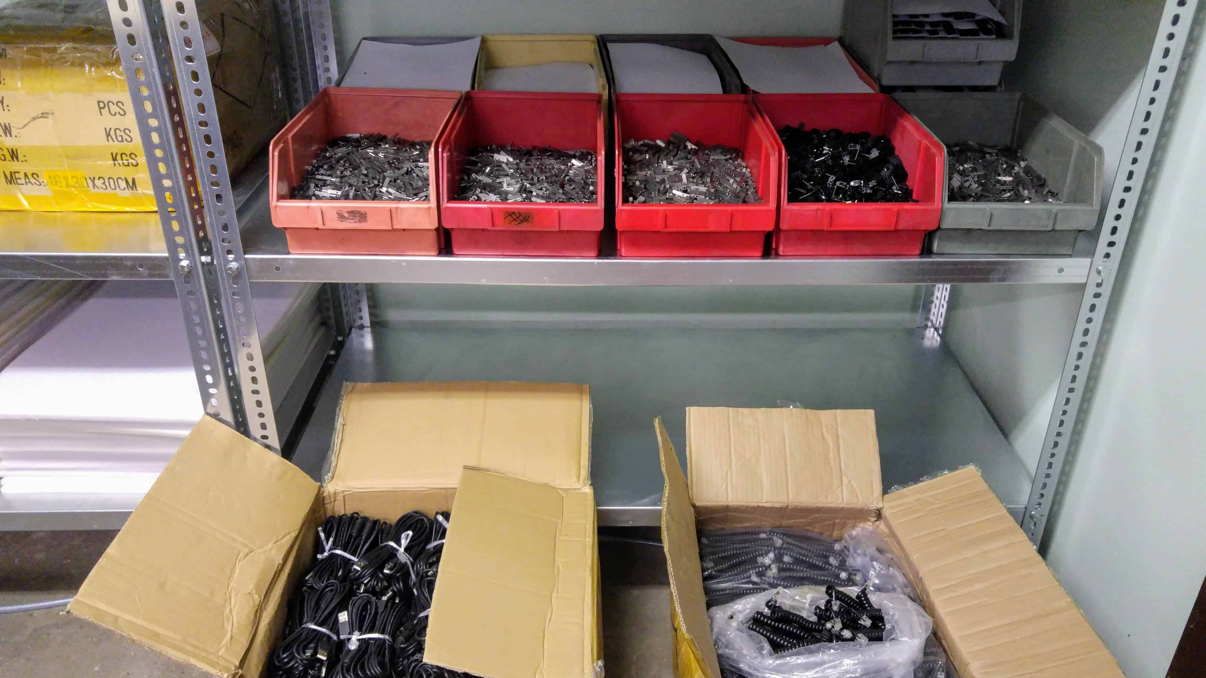
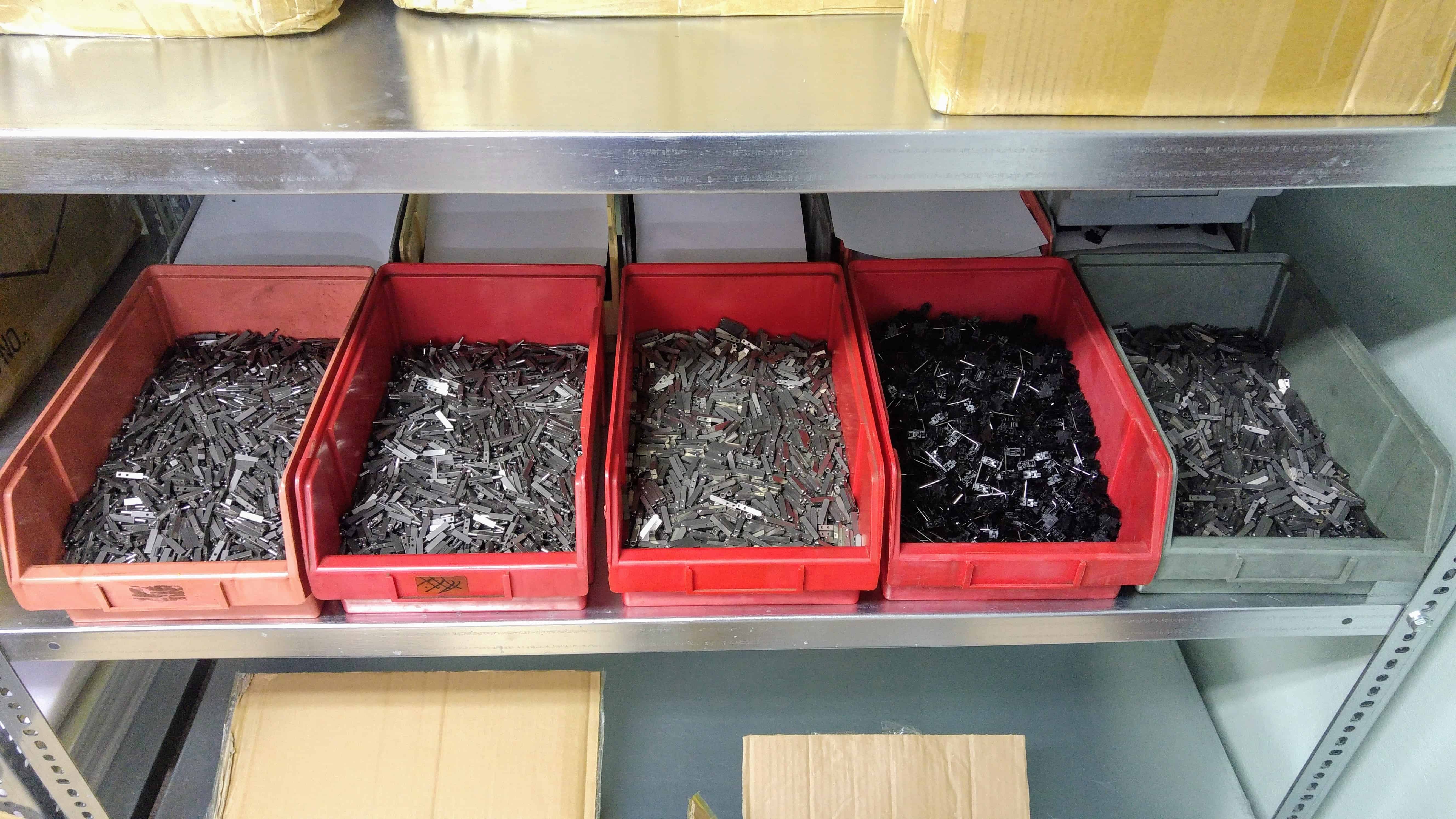
Miscellaneous parts
Lately, some simple but necessary parts arrived from our suppliers, such as the USB cables and the bridge cables. What you see are only some of the many boxes.
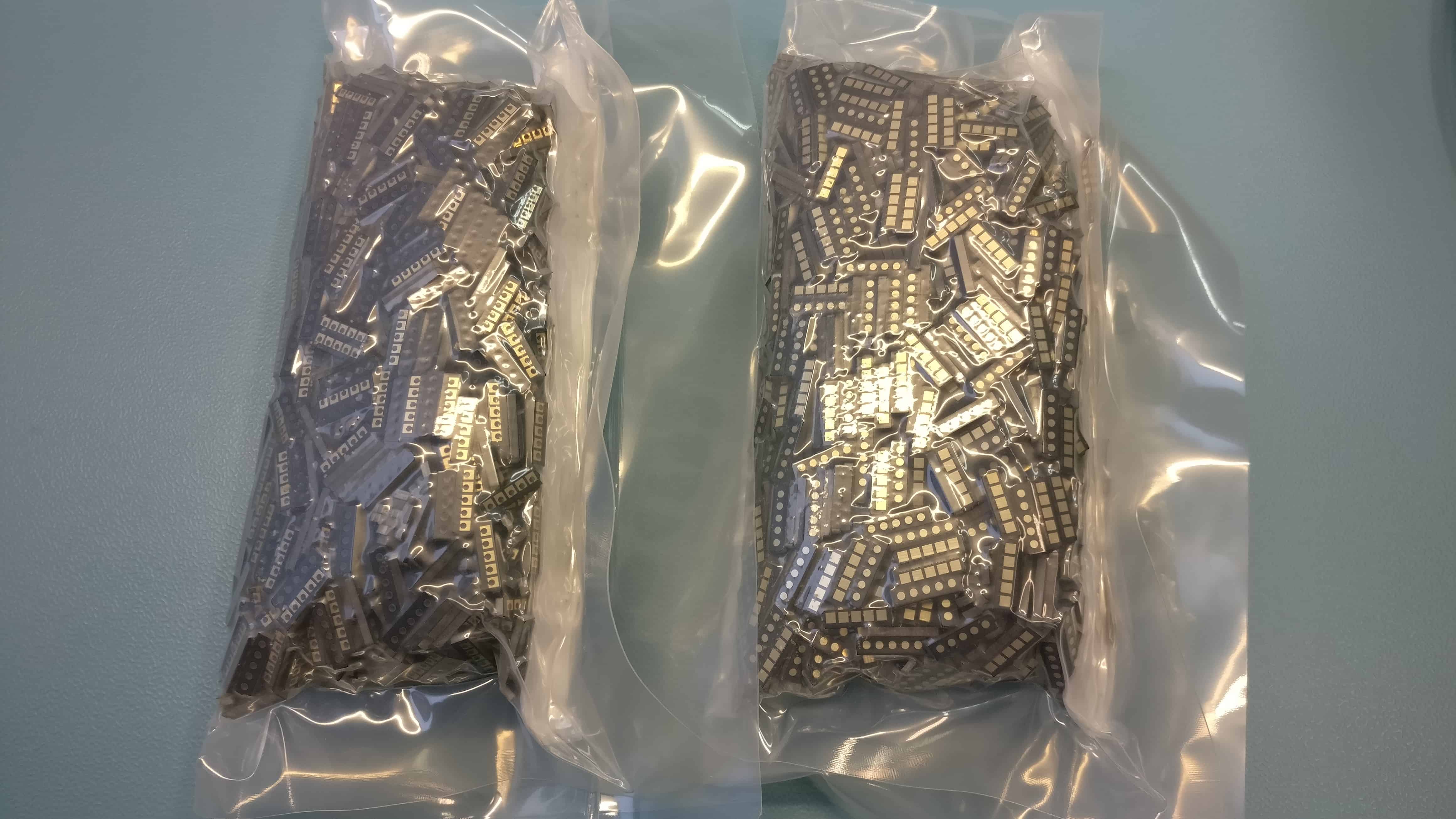
We’ve also finished with the metal guides. There are 16,000 of them.
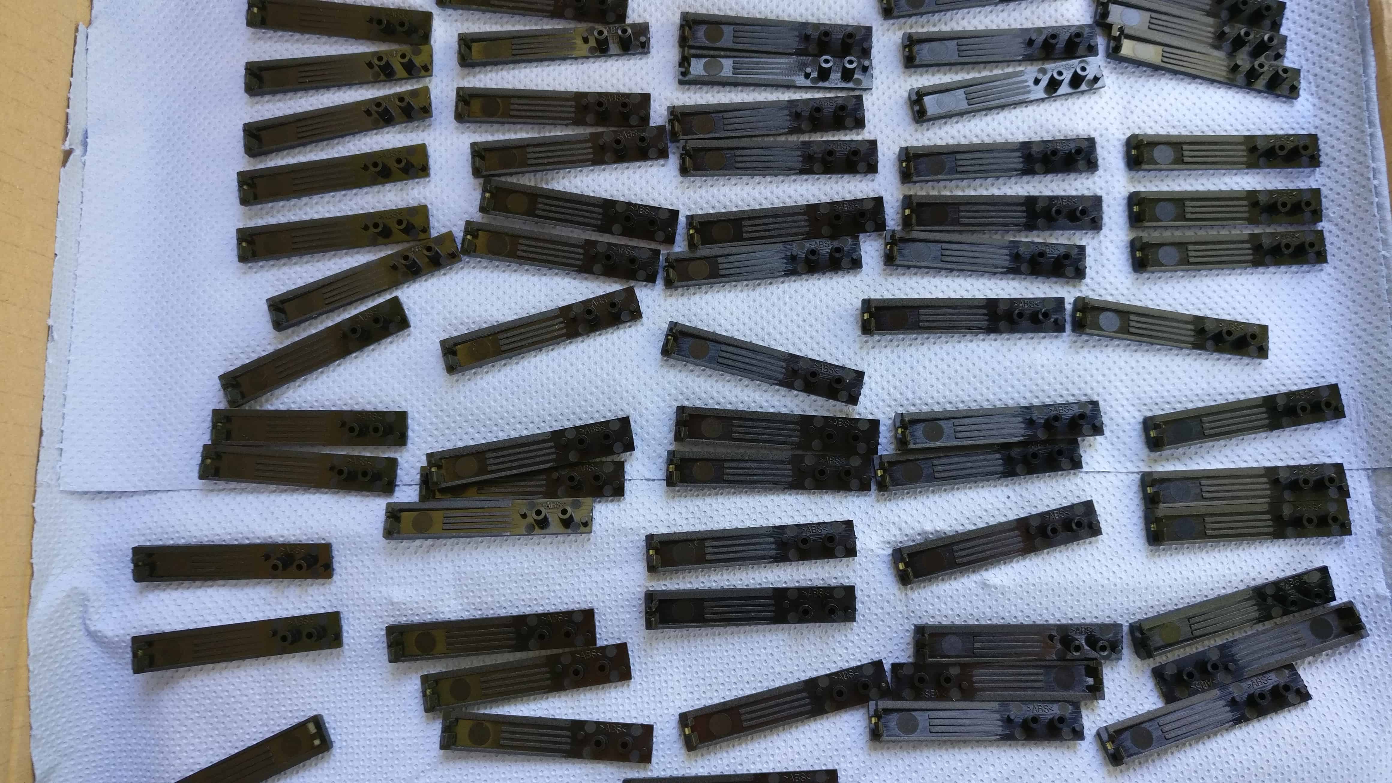
1,300 flip-out feet have been molded.
These are a some of the 5,000 case buttons manufactured so far.
2,000 pairs of vertical PCBs have been fabricated. These will mate with the modules, or with each other when the UHK halves are merged.
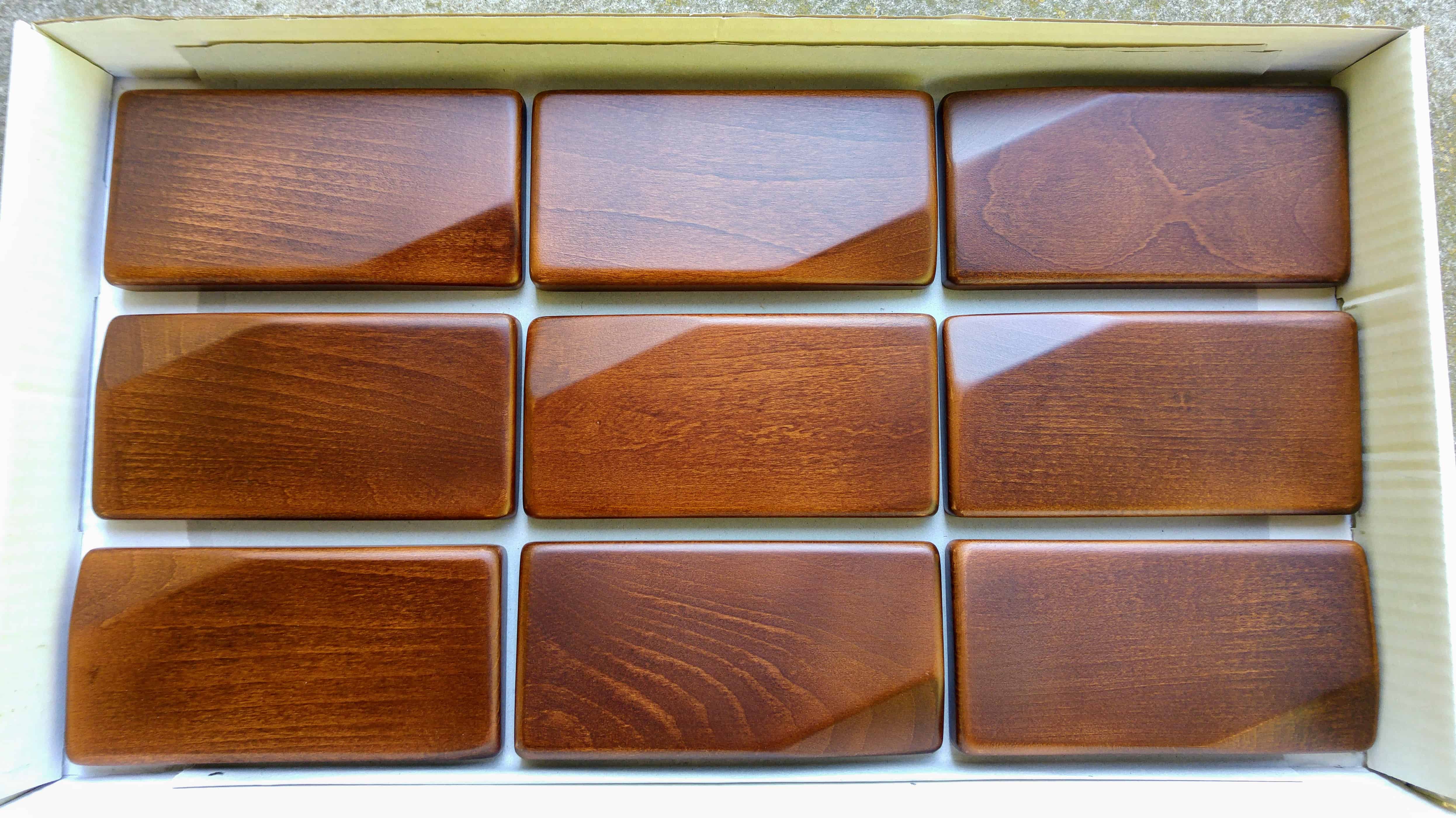
Palm rests
Finally, the palm rests for the pilot run are now ready.
Adding a pair of these palm rests to my prototype truly elevated the overall look and comfort level. It was like putting on the crown jewel.
Luckily, the bypass capacitor related fix that I outlined in our previous update solved the I2C communication issue, even though my initial fix didn’t.
When I soldered the through-hole capacitors to the previous version of our PCB it seemed like a success, but it wasn’t. I realized that communication was still unstable. Then I started emailing back and forth with Eben Qiu, field application engineer of ISSI, and he persuaded me that this must be the issue.
Eben sent me an application note titled AN-035-EN Layout Guidelines for IS31FL3731-SASL2 and a further Layout guideline document tailored to the UHK. Based on his advices, I slightly but carefully redesigned the board around the LED driver ICs. The main thing is that the bypass caps must be put as close to the GND and VCC pins of the ICs as possible. GND and VCC traces must be as thick as possible.
Redesigned PCBs featuring bypass caps close to the LED driver ICs
I’m happy to report that the new layout has made I2C communication rock solid, but it’s still possible that it’ll hang every now and then, so we’ll combat this issue in two other ways.
First, I’ve made sure that the state of the LEDs is cached by the master MCU and it only sends updates to the LED drivers when the LED values actually change. By minimizing the amount of communication, we also give minimal chance to the LED drivers to screw I2C.
Second, we’ll make the I2C driver much more robust, so that it’ll be able to recover immediately from errors. Only this solution will result in true robustness.
Having the chance to give the board more attention, I also improved the acoustic noise of the UHK. The noise level was already better than it used to be a while ago, but a subtle high-pitched noise could be heard in a very silent environment. Fortunately, Eben also shared another application note with me titled AN-012-EN Reduce acoustic noise of IS31FL3236 EVB.
I ended up using tantalum electrolytic capacitors instead of ceramic capacitors, which outperformed my wildest expectations in the acoustic noise department. The newest boards are so silent that I cannot hear a damn thing, even when putting my ear as close to the keyboard as possible. And that’s when every LED is driven with full power, which would generate the most noise.
Next up, we went to TÜV Hungary to conduct final measurements at their lab. We finished in the record-breaking time of an hour for both of our prototypes, with the best results so far, and then left the prototypes there. They will send them to TÜV Netherlands for final FCC and CE certification. We should have those papers soon.
Finally, I sent the gerbers to our PCBA contractor, and they started fabricating the boards of the pilot run.
Firmware progress
We’ve already had a fair number of talented contributors, and it looks like we keep attracting some of the best talent, and this time truly one of the best in the world.
The name of our most recent contributor is Erich Styger and his name is familiar to everybody who has ever worked with Kinetis microcontrollers. That’s because if you search for a Kinetis related issue, you’ll bump into one of his blog posts as the first result which usually also contains the solution to your problem.
Erich started out as a compiler engineer, then accumulated more than 20 years of experience as an embedded systems engineer, and now he works as a professor at the Lucerne University of Applied Sciences and Arts, and works with the ETH Zürich, and also for NXP. His MCU on Eclipse blog is the go-to place for everything Kinetis, and many consider him the world’s most knowledgeable professional in this space.
As you can imagine, Erich is very busy, but over a fair number of emails I’ve managed to persuade him that the UHK is the best thing since sliced bread, and given the development capabilities and open nature of our keyboard, he became quite interested in it. So much so that he allowed me to send him a prototype, then he sent us his fair share of contributions.
Every one if his contributions is a definite step forward, but the one I consider the most valuable is his BusPal fix, as it finally enables the right side firmware to route the firmware to the left keyboard, allowing us to upgrade the firmware of both keyboard halves, and coincidentally the firmwares of the modules, too! He’s also written a relevant blog post on his blog.
Mad props and a pilot run UHK with a palm rest goes to Erich. I feel fortunate, thrilled, and honored beyond words to have him contribute.
Meanwhile, Eric (not Erich), our intern has been hard at work and finished fully implementing the configuration parser. He also started implementing the macro engine. Unfortunately, his internship period is over, so the macro engine is not ready yet, but he was making great progress which I’m very happy about. Thanks so much for your hard work, attention to details, and diligence, Eric!
With the configuration parser in place, the UHK is able to switch across keymaps which was the last major remaining parser related issue. The macro engine will not entirely be ready by the time of the pilot run, but we’ll be gradually shaping it, and it should be ready in the not so distant future.
In the meantime, I implemented an async I2C EEPROM driver, so now the firmware is able to transfer the configuration to and from the EEPROM, enabling the UHK to persist the configuration.
Estimated delivery and standing issues
These are the major standing issues that affect the delivery of the pilot run:
Top case parts: We’ve already molded numerous cases, but we’re still working on improving the surface quality of the top parts. The molds should be ready in 1-2 weeks at which point we’ll manufacture 150 pairs of them.
Packaging and back stickers: We’ve been working a lot on the design of the packaging of the UHK and the palm rest and we believe they’ll be very fancy. We’ve ordered 3,000 UHK boxes and 1,500 palm rest boxes which may take 3-4 weeks to be manufactured but hopefully we’ll be able to get some of them earlier for the pilot run.
PCBs: The PCBs are being manufactured and are expected to be ready in August. Then our PCBA contract manufacturer will assemble 50 of them for the pilot run.
FCC and CE certification: We don’t have a solid ETA about this, but chances are good that this will be done by the end of August.
The bottom line is that we’re doing absolutely everything we can to deliver the pilot run by the end of August.
Thank you for reading this update! As always, we’ll be keeping you updated on a monthly basis via our blog and newsletter.
Hi there, and welcome to our monthly status update!
TL;DR: We’re making rapid progress with the assembly process. The firmware and Agent have matured significantly and become truly cross-platform. We have to make a minor design change on the PCB that will set us back by 2 weeks. Batch 1 has sold out and batch 2 will ship starting December.
You can always check out the expected delivery date and update your shipping address on your Crowd Supply account page.
Batch 1 has sold out
Given the uninterrupted pre-sales period since the end of our campaign, the first batch of 2,000 UHKs has just sold out. That means that going forward, new orders will fall into batch 2 which can be expected to ship in December.
Your orders will still be served on a first-come, first-served basis, but this delay between batch 1 and batch 2 is inevitable as we ramp up production.
Starting from batch 3 we expect to have a decent stock, so we’ll be able to provide you UHKs without any delay.
The inner assemblies are coming together
The inner assembly is comprised of a number of parts that reside inside the UHK case.
16,000 metal guides are already made. We'll have to press-fit the pins into half of them. Speaking of the pins, we’ve further optimized them. We’ve switched to using pins with spherical ends and a hardened surface, resulting in a heavenly smooth, yet solid merge-split experience. Perfecting these guides was an art unto itself.
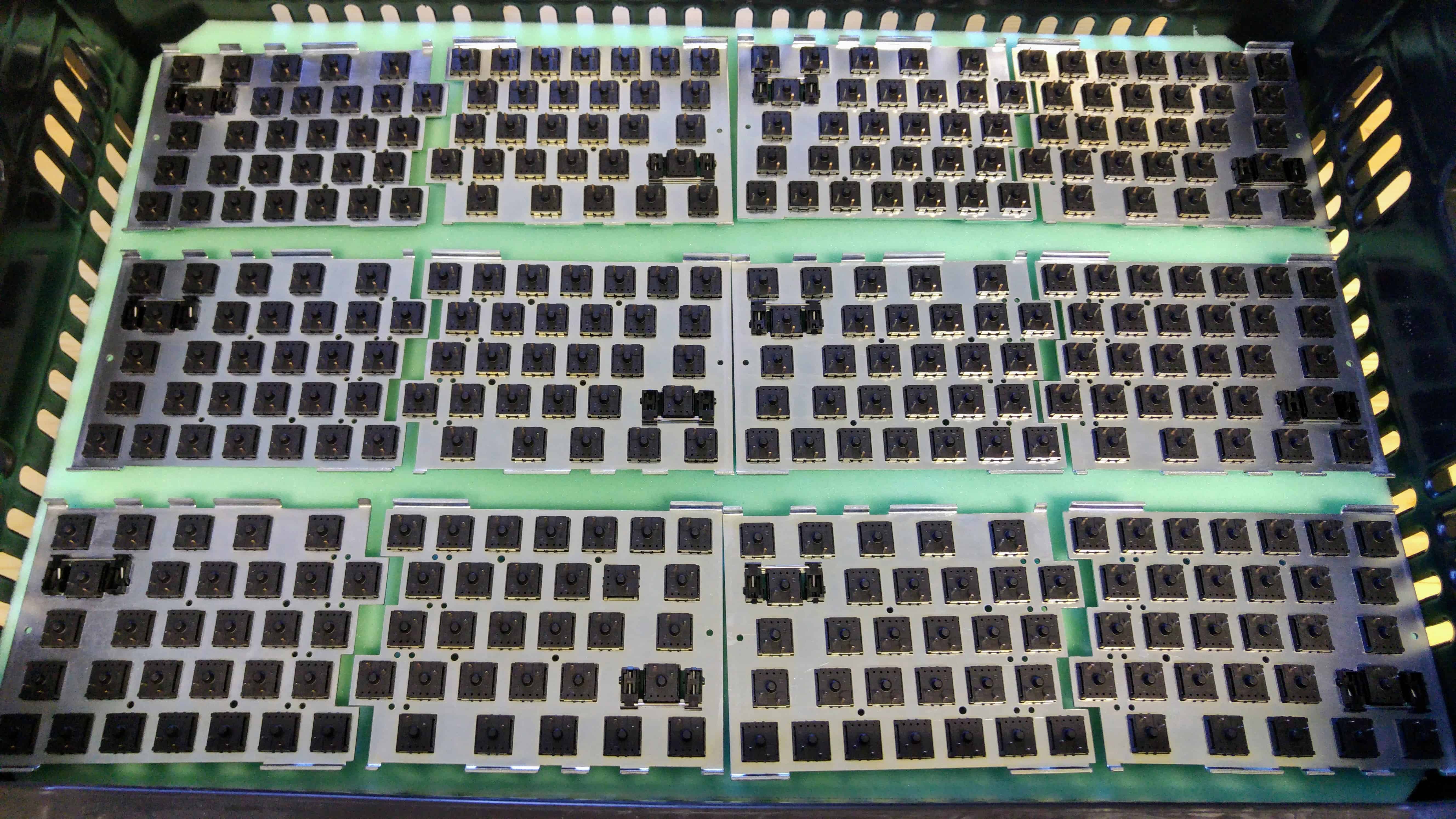
600 pairs of plates have been manufactured and zinc-plated.
We’ve learned that seemingly mundane parts like keycap stabilizers can take surprisingly long time to assemble. There are two identical left and two right parts that slip together, then a metal wire is inserted into them. Thankfully, we’ve already finished assembling 5,500 of these.
The above results in assembled plates like these.
Assembled plates, front sideAssembled plates, back side
So far, we’ve assembled 150 pairs of plates, and 50 pairs of those will be used for the pilot run. These plates will travel to our PCBA contract manufacturer who will solder them together with the PCBs. Afterwards, the guides will be screwed to the plates, completing the inner assemblies.
Outer assemblies and miscellaneous parts
As you can imagine, one of the most complicated parts are the plastic cases. So far, we’ve manufactured 150 pairs of bottom cases, and 2,000 pairs of case buttons.
Left bottom casesRight bottom casesCase buttons
The molds for the upper cases are being tweaked and we expect them to be perfected within 1-2 weeks, at which point we’ll put them to good use and manufacture 150 pairs of top cases.
Apart from the above, there are still a fair number of parts that go with the outer assemblies including the magnets, magnet-counter parts, rubber feet, inserts, back stickers, and a couple of screws.
Since our last update, we’ve also ordered 2,000 USB cables and bridge cables. Fun fact: the total length of these USB cables is 3.6 kilometers, or 2.23 miles.
Firmware progress
The firmware already works pretty well, but the configuration parser was very basic a month ago, only capable of parsing layers. It was clearly incomplete because it should parse not only a single layer, and not even a single keymap, but the fully-fledged binary configuration containing a set of layers, macros, and various items.
To my surprise, I received an email about a month ago from Eric Tang. Given his passion for keycaps, we’ve already exchanged numerous emails with Eric, but this email was different.
Eric asked me whether we have an internship program. He caught me by surprise and even though we’ve never had an internship program, I asked him what was on his mind exactly. As it turned out, Eric has written his own keyboard firmware based on AVRs and LUFA, making him the perfect candidate to develop the configuration parser of the UHK.
Since then, Eric has made tons of progress and now the firmware is able to parse almost the whole UHK configuration except macros. He’s now working on making the LED display show the abbreviation of the actual keymap, and then he’ll finish off macros, and develop the macro engine.
I feel very fortunate to have been contacted by Eric, and am having a great time working with him. The configuration parser shall be implemented soon!
Agent progress
Quite a few things have happened with Agent.
Right after Eric started working on the configuration parser, he couldn’t make Agent work on his Mac. I originally believed that it’s a privilege escalation issue, but Robi investigated further and realized that it’s a much deeper problem.
As it turned out, libusb, the library we used to make Agent talk to the UHK via USB isn’t supported on the Mac anymore. Apparently, recent OSX versions implement a new version of the USB subsystem which broke libusb.
Luckily, Robi found hidapi, the perfect alternative for libusb. In his true fashion, he didn’t waste his time, and ported Agent to use from libusb to hidapi. As a result Agent now runs perfectly on all the three major OSes.
Now, there’s only portability problem to be solved. blhost, the command line utility that updates the firmware of the UHK also utilizes libusb and it segfaults on OSX now that libusb is broken on Mac. Unfortunately, NXP doesn’t seem to care but fortunately, Santiago made me aware of pyKBoot, a python command line application that speaks the kboot protocol just like blhost, but which uses hidapi instead of libusb. I’ve toyed with pyKBoot a bit, and looks like it’s a viable alternative to blhost.
I think we can use pyKBoot but I’m not fond of it because we’ll have to package it as a standalone, self-contained executable, possibly using PyInstaller which will likely make the bundle size of Agent considerably larger than optimal. I’d really like to replace pyKBoot eventually with something more native to Agent. I think the best way forward is to port pyKBoot from Python to TypeScript later down the line.
Speaking of other parts of Agent, Robi has also implemented an auto-update mechanism. We have yet to refine it, but it seems to be already working.
Józsi also implemented a more general rendering mechanism for Agent, enabling it to render both ANSI and ISO keymaps according to your UHK version.
Electronics issues
Few days ago, I started to heavily test my backlit UHK prototype and found a serious issue. For some reason, the communication between the keyboard halves interrupted from time to time and eventually died.
Frustrated but determined, I delved into the issue and figured that it was caused by the LED drivers. When I disabled the LEDs, the prototype was rock stable. I further narrowed the cause, and found that the issue only surfaced when I enabled one of two LEDs, the LED of the right Alt key or the LED of the comma key.
I couldn’t make sense of this, so I got in touch with Integrated Silicon Solution Inc., the manufacturer of the LED driver ICs that we use. As it turned out, we didn’t place the bypass capacitor of the LED driver close enough to the IC. I soldered a through-hole capacitor as close as I could to the LED driver on my prototype and it solved the issue in no time.
Even though we don’t provide a backlit UHK version yet, many of you have expressed your desire to solder LEDs to your UHKs, so this is a big deal. Even more importantly, we already utilize the left side LED driver to drive the LED display and even though it didn’t produce such issues in itself, I fear that such issues could surface on a quite a few UHKs out of 2,000 UHKs, so this issue must be resolved.
Admittedly, this sucks, but thankfully, it’s a very minor PCB redesign which I’ll implement in about a day. We will, however, have to get new prototype PCBs made, assembled, and tested, so it will translate to a 2 week delay.
If there’s someone to blame, I surely am. I should have tested this way earlier. I’m sorry about this, but I’m also thankful because TUV hasn’t started testing our prototypes for the certification process and our PCBA contractor hasn’t started to manufacture the PCBs for the pilot run yet. I sent them notice just at the last minute. If I didn’t, we would have lost a lot of money due to this issue.
All things considered, even despite the PCB redesign, we’re getting very close. Pilot run notification emails will be sent out soon, followed by 50 UHKs, and followed by the rest of the 1,950 UHKs of batch 1. We cannot wait to finally ship!
Thank you for reading this update! As always, we’ll be keeping you updated on a monthly basis via our blog and newsletter.