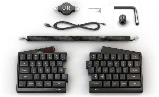
If you've checked out our site then you must already have a good idea of what you can expect to have when your package gets shipped. Regardless, we thought that we should clarify what's in the box by creating a nice illustration and listing the items one by one.
From top to bottom:
Retractable cable: 1 meter long when expanded, featuring 6P4C RJ11 connectors
Lock screw and hex key for permanently interconnecting the keyboard halves if you happen to prefer a one-piece keyboard.
USB Mini-B to A cable: 1.8 meters long
Spring cable: 0.35 - 0.65 meter long, featuring 6P4C RJ11 connectors
Left and right keyboard halves
We've already said some words about the permament interconnection mechanism, but no words have been said about the spring cable, so here it goes:
We provide an extra spring cable besides the retractable cable because some of you have expressed concerns regarding the durability of retractable cables. We've talked to a number of retractable cable manufacturers and we think we have chosen a reliable one but just to address your concerns we will provide a spring cable, too.
Security is a serious business but more often than not it gets overlooked. Ideally, it should be part of the design from the get go but people are prone to overlook it given the huge number of seemingly more urgent issues to be taken care of. That's why it's a blessing when you get contacted by a security consultant like Marcus Gustafsson out of the blue.
Marcus expressed his concern regarding the security of firmware upgrades and we exchanged a couple of lenghty emails full of geek talk. I originally planned to copy-paste all of them here so that everybody can see the gory details but that'd be a very long post so I'd rather just summarize what really matters.
Given his security-conscious mindset Marcus wanted to have a dedicated physical port to upgrade the firmware. He said that he rather would not want to rely on perfect code but enforce a hardware level security mechanism for firmware upgrade purposes so that no unwanted firmware can be uploaded by malicious applications. Originally, I couldn't see a way of making it happen but he was diligent enough to look into AVR datasheets, found the lock bits and ultimately, we figured out a way.
I ended up defining the following 4 security modes:
In insecure mode after the keyboard received the USB bootloader jump control request it immediately jumps to the bootloader. Malicious applications rejoice!
In confirmation mode after the keyboard received the USB bootloader jump control request it captures key input and waits for the "1q2w3e4r5t" confirmation string in order to jump to the bootloader. In this case malicious applications cannot make the keyboard jump to the bootloader without the user explicitly permitting the operation by typing a word, captured by the keyboard. This mode will be the default.
In secure mode after the keyboard received the USB bootloader jump control request it captures key input and waits for a password that was explicitly set up by the user beforehand. The password is stored in the EEPROM as a cryptographic hash. Not only an explicit user interaction is necessary to enter the bootloader but the user must know the exact password.
In locked mode the lock bits of the microcontrolers are set and as such firmware upgrades through the bootloaders are not possible. A dedicated hardware programmer must be used for setting the lock bits and uploading the new firmwares. Connecting the programmer to the programming header requires the disassembly of the keyboard which means unscrewing 2 screws per keyboard half and taking apart the top and bottom part per keyboard half.
I think the above modes should cover enough ground to satisfy the need of every user from the least security conscious to the most. There are only a handful of keyboards on the market whose firmware is upgradable and out of those keyboards every one implements the insecure mode detailed above. I'm excited that we're the first to address this problem!
Lastly, let me just re-emphasize how much your voice matters. Thanks to Marcus the UHK can be better than any other keyboard security-wise. Have a great idea, a critique or concern? Please let us know! We're doing our best to address every issue.
Based on our video and images you must already have a good idea of how the Ultimate Hacking Keyboard looks like. We thought why not take this experience to the next level and provide a 3D model that you can rotate, zoom and pan. You can also go fullscreen and cycle through the annotations. Go crazy!
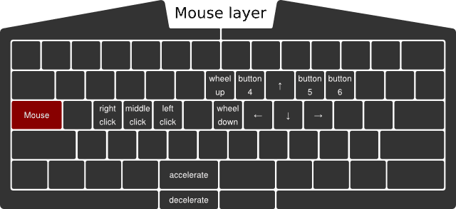
When I created the mouse layer, I was thinking about adding a boost key to increase the pointer movement speed while it's pressed. It'd allow for faster navigation when large distances need to be traveled by the pointer. I also immediately thought of the left Mod key as the ideal candidate for this purpose. Shortly, I dismissed my idea thinking that Mod is a layer switcher key, and as such, it should only serve one purpose not to overcomplicate matters.
Lately, we've been contacted by two of you, independently suggesting to add a feature akin to my original boost concept. I honestly cannot remember the name of the first person, but I can clearly remember the second of you, Christian Léger, who has suggested not only to enable users to increase mouse speed but also to decrease it for finer-grained mouse interactions. At first, I was a little hesitant, but ultimately, I do think that acceleration and deceleration complement each other very nicely and improve usability, so hence here's the updated mouse layer.
Given the normal, user-configurable speed of the mouse pointer, the accelerated speed can be 2x, and the decelerated speed can be 0.5x of the normal speed, for example, all being user-configurable values.
But there's an important question to be answered: What if both the Mouse and Mod keys are pressed simultaneously? Which layer switcher key should dominate choosing the layer to be used? Easy: let's put the layer switcher keys into a priority list, defaulting to Fn, Mouse, and Mod. I'm not fully confident about the exact order, but in any case, the UHK being a fully configurable keyboard, this priority list will be configurable on a per-keymap level.
Update (2016-07-29): We'll ditch the priority list in favor of a much easier solution: Whichever layer switcher key gets pressed first will be the active one (active layer) until release.
I've also made some other fixes. First of all, I added "button 6", which was missing. Second, I replaced "history prev" with "button 4" and "history next" with "button 5". The original naming of these keys was based on the function of those keys within browsers, but the more generalized naming is clearly better.
We're infinitely grateful for people like Christian who have taken the time to share their thoughts. Believe it or not, even when you ask questions quite often, you make us learn and sometimes reiterate our design. This blog post is the evidence that you can make a change, and we're listening to you. Let's push things further than ever and make the Ultimate Hacking Keyboard a truly remarkable keyboard!
Reducing hand travel distance during typing is a big deal. So much so that we thought that it's important to show you the substantial difference of hand movements distance when using the Ultimate Hacking Keyboard vs a regular keyboard using animations. The result can be seen on our main page.
If you take a look at these animations they may look deceptively simple and in essence they are but the road that leads to them is quite bumpy. Let me share the ride.
When it comes to animations animated GIFs are the first thing that probably pop into most people's minds. Unfortunately, they tend to be very large files that download slowly, especially in the case of high-resolution animations featuring high frame rates. But what alternatives exist?
SVG! Unlimited resolution, unlimited frame rate, minimum size. SVG is great but just like in the case of videos it's quite tricky to make them responsive. Thank God there are some excellent writeups out there explaining how to make SVGs responsive.
I really wanted to define SVG animations in a declarative manner so I went with SMIL which stands for synchronized multimedia integration language. It's essentially a set of tags and attributes to describe animations within SVGs. It wasn't trivial to chain a sequence of animations together but eventually I made it work. Then came cross-browser testing and the realization that Internet Explorer (unsurprisingly) doesn't support SMIL. No problem, there's a polyfill for that! Except that it doesn't work well so SMIL can go down the toilet.
Snap.svg to the rescue! I put distinctive IDs on the various elements to be animated. The most important objects are the left hand and right hand elements and there were a couple of target points outside of the alphanumeric area of the keyboard for the hands to reach out. Being able to animate things algorithmically, I randomized hand movements which resulted in a lively moving pattern that is quite enjoyable to watch.
Cross-browser testing revealed a bug that was hard to debug: On the stock Android browser when scrolling downwards only the first SVG started to animate, all the others were not moving. I used Weinre to debug this issue and it turned out that the stock Android browser didn't like that I reused the same IDs in distinct SVGs. Inline SVGs are all part of the same DOM so this is somewhat understandable even though other browsers handle this situation well. Another weirdness is that when reloading the page in the stock Android browser and scrolling from the bottom towards the top the animations start as expected. Anyways, I ended up using classes instead of IDs to match elements which solved this problem.
I noticed that animations were always running on the page, burning the CPU all the time so I started to think how to reduce CPU usage. jQuery inview plugin to the rescue! I wanted to explicitly pause / resume animations when they go outside/inside of the viewport. For that ideally one should use the pause() and resume() methods of the mina object, except that Snap.svg is buggy in this respect so I ended up using Element.stop() and Element.animate().
I also wanted the animations to lazy-load when the user scrolls before them by 200px but this the jQuery inview plugin didn't support offsets. Luckily, I found an unmerged pull request in the repo that implemented this exact feature. Lazy-loading SVGs doesn't exactly work the way it does with traditional images because when animating SVGs, they must be included inline for the individual SVG elements to be separately accessible in the DOM. I could make this work with Snap.load() and Element.append().
Animations are buttery smooth on desktop machines but rather jaggy on mobile devices. It understandable because SVG animations are quite computationally intensive, especially when there are more of them in the view and are topped with JavaScript code that computes target coordinates real-time. Unfortunately, I cannot improve the situation any further.
"Was it worth all the hassle?" - you may ask. Even though it started as a simple addition to the site it consumed a significant amount of my time which could have been better spent on designing the next prototype. A part of me wishes to recover the time spent but on the other hand I'm a firm believer that it's critical to present products and ideas in the most digestable and intuitive way possible for the people to get their essence. In this very spirit it wasn't a waste of time after all but I surely don't wanna touch the site for a while.
Hope you enjoyed this writeup. I'm back developing the next prototype along with András. We're gonna make another significant improvement to the site soon (which won't consume my time) and we expect it to blow people away. Excited![/fusion_builder_column][/fusion_builder_row][/fusion_builder_container]
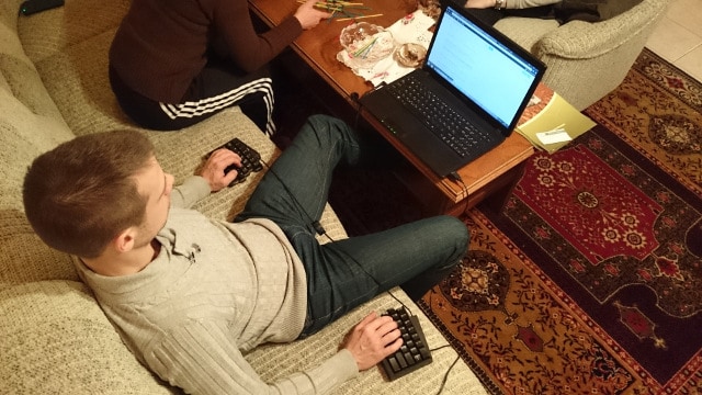
Instead of hunching over the laptop Laci is typing (and controlling the mouse pointer) in the most laid back fashion ever. A perfect use case of the Ultimate Hacking Keyboard. A more ergonomic working environment is surely preferred on the long run, of course.
We're happy to report that the PCA9634 IC that controls the columns of our LED display is now working as expected. This was a tricky case to solve so let us share the journey of finding the solution.
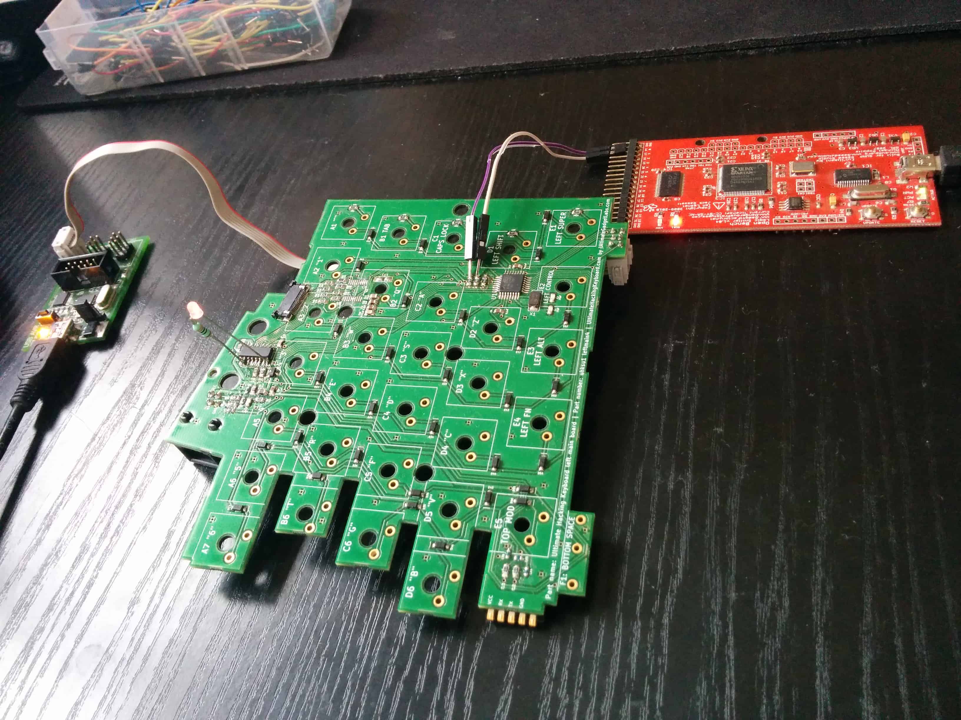
When starting to debug the problem it was rather strange that the Bus Pirate almost exclusively showed START and STOP bits but almost no actual payload. This shouldn't have happened because the I2C bus was clocked at 400kHz and the Bus Pirate should be able to decode 400kHz I2C communication because this very frequency can be selected from its menu. I still don't know what's wrong with my Bus Pirate but I ordered a new, more modern one which is on its way. Looking for alternative ways to track down the issue I broken out SDA and SCL, added a status LED to the board and reached for my Open Bench Logic Sniffer.
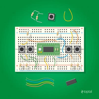
[fusion_builder_container hundred_percent="yes" overflow="visible"][fusion_builder_row][fusion_builder_column type="1_1" background_position="left top" background_color="" border_size="" border_color="" border_style="solid" spacing="yes" background_image="" background_repeat="no-repeat" padding="" margin_top="0px" margin_bottom="0px" class="" id="" animation_type="" animation_speed="0.3" animation_direction="left" hide_on_mobile="no" center_content="no" min_height="none"]Sniffing the I2C communication of the left keyboard half with the Open Bench Logic Sniffer
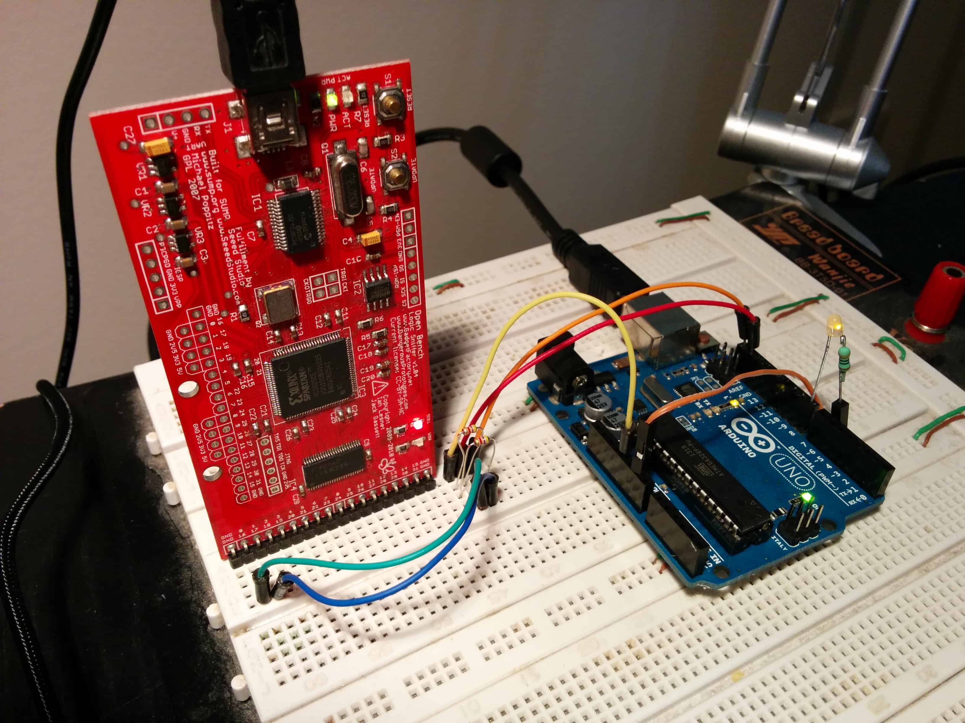
The signals that were analyzed by the sniffer were a mix and match. Sometimes the analyzed I2C communication made sense but other times it was riddled with protocol errors. Also, the strange thing was that I2C often hanged for some reason at which point I reached to the AVR freaks to help me. They suggested that I should not use I2C from an interrupt handler which I clearly shouldn't but this code has worked on an Arduino before so I knew this wasn't the core reason. It was time to switch to an Arduino to better able to debug the problem.
[/fusion_builder_column][fusion_builder_column type="1_1" background_position="left top" background_color="" border_size="" border_color="" border_style="solid" spacing="yes" background_image="" background_repeat="no-repeat" padding="" margin_top="0px" margin_bottom="0px" class="" id="" animation_type="" animation_speed="0.3" animation_direction="left" hide_on_mobile="no" center_content="no" min_height="none"]Using an Arduino Uno to further diagnose the problem
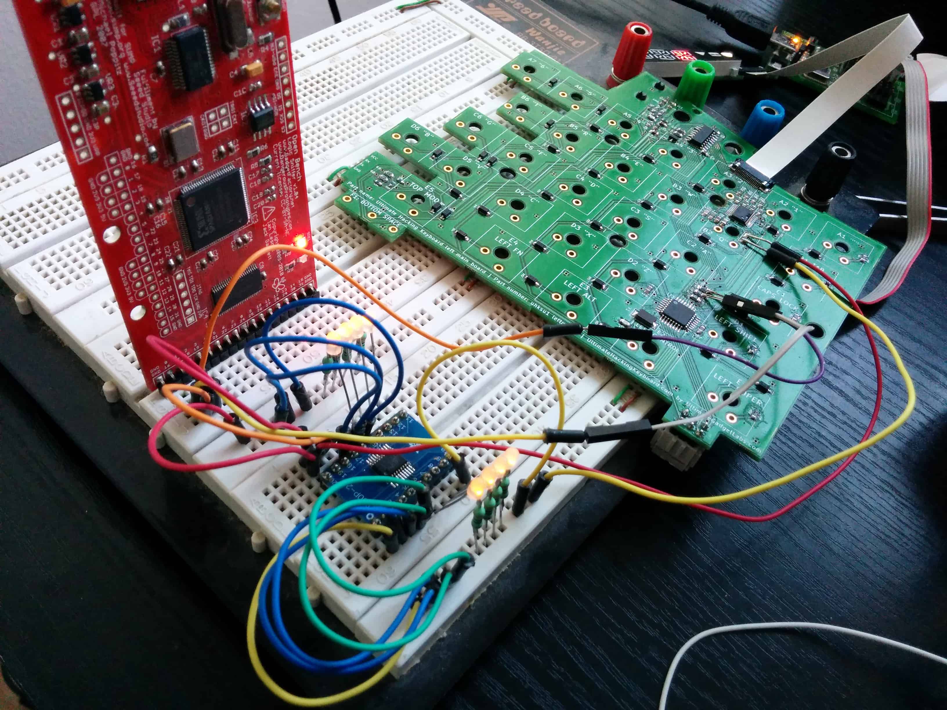
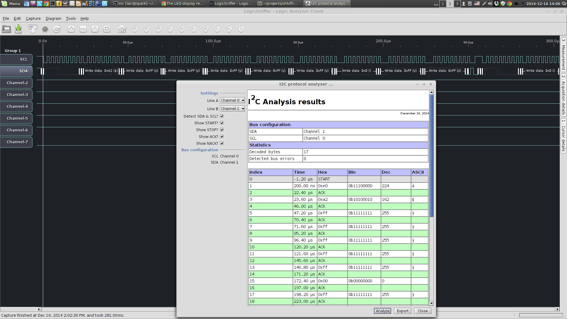
Initially, I haven't had any 4.7K PTH resistors laying around for pulling up SDA and SCL but had some SMD ones so I made DIY PTH resistors by soldering wires to pads of 0805 SMD resistors. The sniffed signals were still full of protocol errors. I eventually managed to get PTH resistors which probably made my circuit more reliable but most importantly I realized that the 1Mhz sampling frequency that I used with the logic sniffer was barely sufficient to sniff the 400kHz I2C resulting in frequent decoding errors.
Documentation mentioned that the sampling frequency should be at least 10x larger than the frequency of the bus to be sniffed. After making the proper adjustment I was finally able to consistently see communication clearly, both inside and outside of the timer interrupt handler. That was the perfect moment to grab the working firmware and go back to the left keyboard half to test things there.
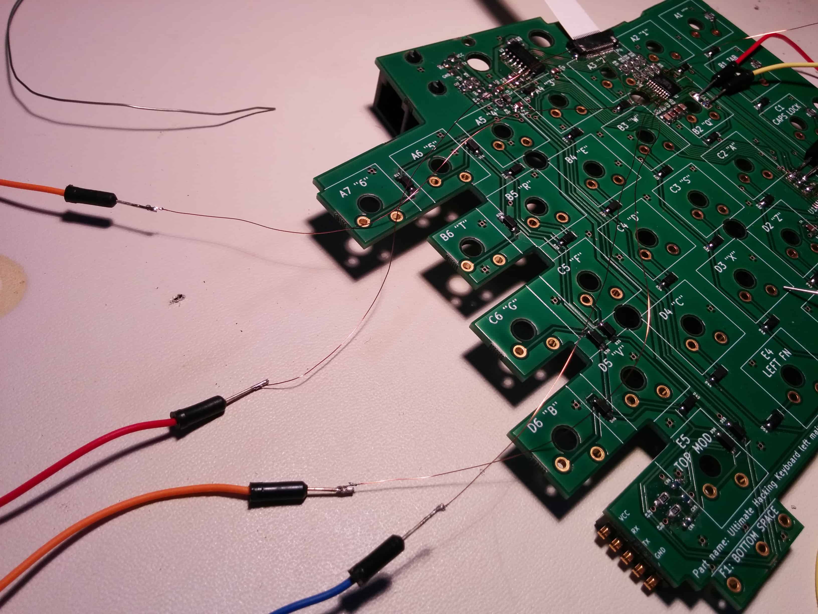
This time I broke out not only SDA and SCL but VCC and GND too to interface with an external PCA9634 that was soldered onto a breakout board. Even though initially I couldn't control the LEDs that were wired to the external PCA9634 but the sniffer showed me that that an ACK was received after sending the address of the PCA9634 which was very encouraging.
After messing around with the code I finally realized that there was a critical bug in it. I shifted the bits of the auto increment flags not by 5 bits as described by the PCA9634 data sheet, but by 4 bits! This resulted in sending invalid register numbers that didn't make the IC do anything useful. After fixing this issue the LEDs started to toggle as expected and the sniffed communication looked great, too.
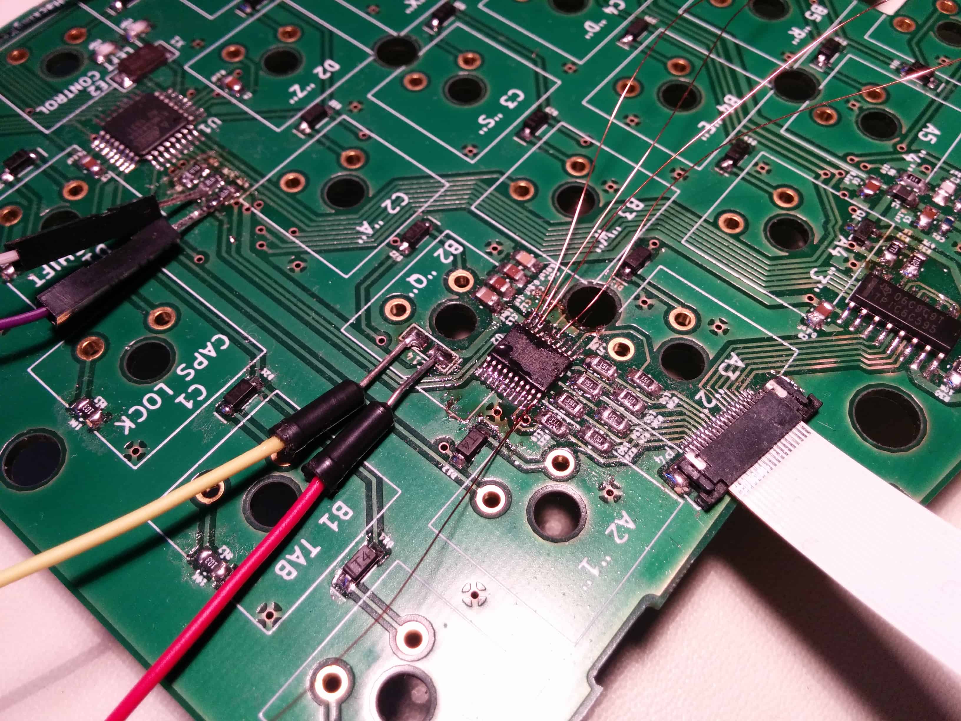
At this point both the external, broken out PCA9634 and the internal one was wired to the MCU but only the external was working. It was apparent that this is some sort of an electrical problem. My best idea was to connect the SDA, SCL, VCC, GND and OE lines of the external PCA9634 right to the pins of the on-board PCA9634 instead using the previously installed wires. By replacing the connections one by one I should be able to figure out which connection is the bad one.
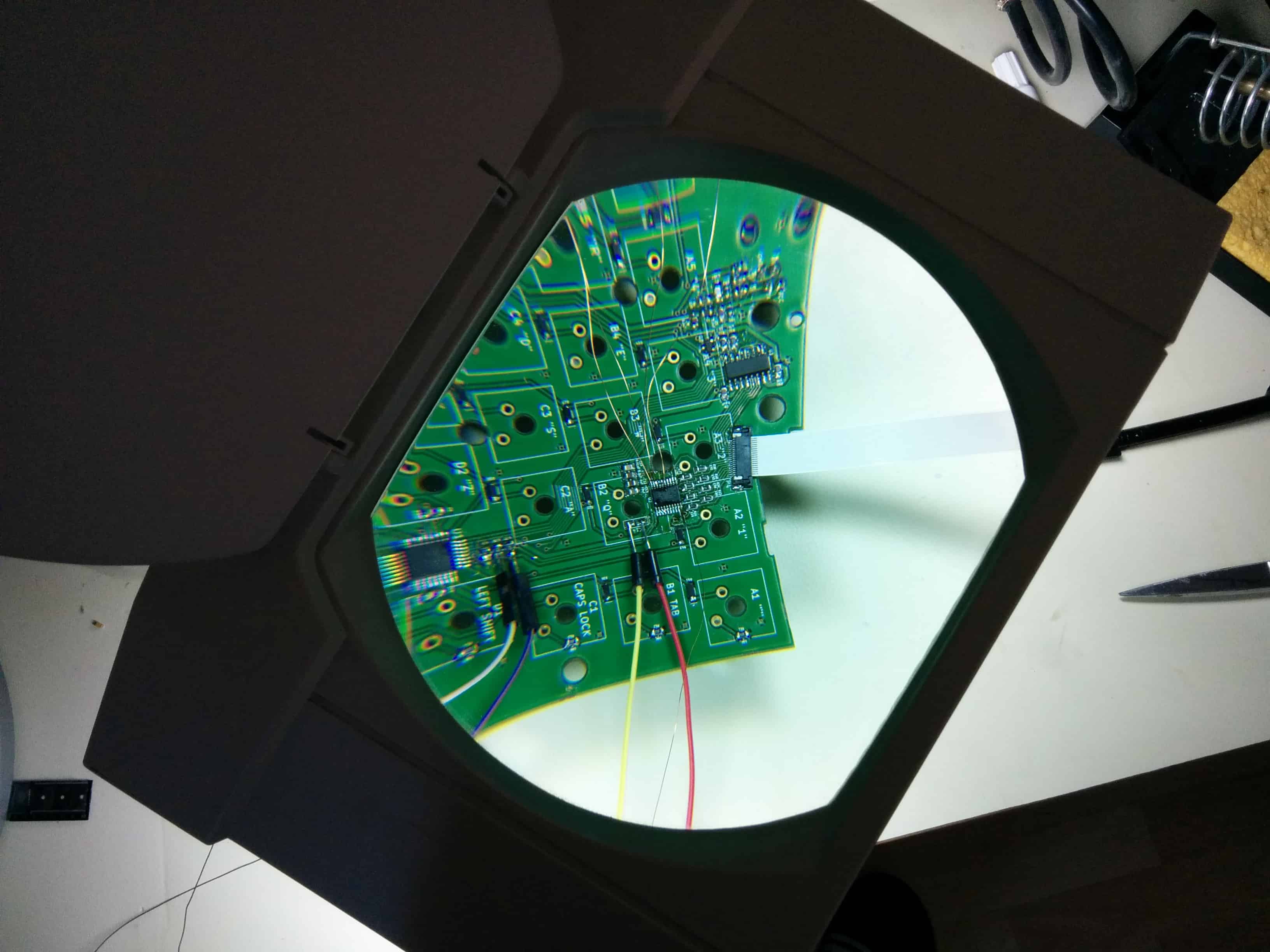
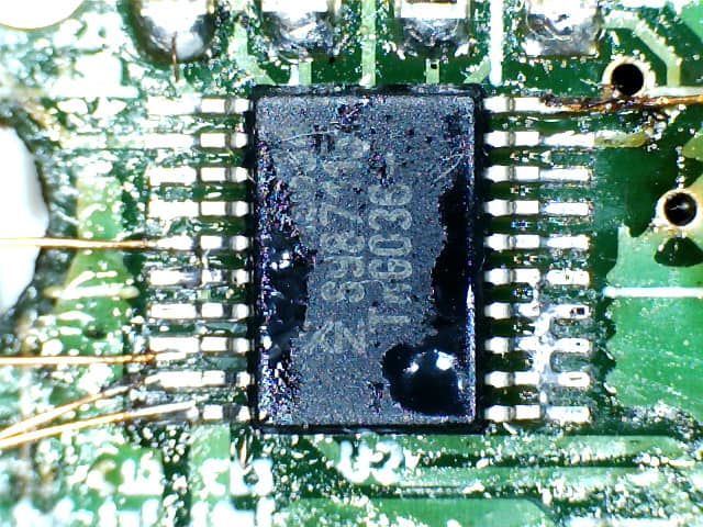
Accessing the pins of the TSSOP packaged PCA9634 was rather hard, being merely 0.65mm away from each other. My only option was to use my wiring pen to solder enamel wires right to the pins of the on-board IC. Eventually, I managed to break out the connections right at the pins of the IC.
When powering up the board something unexpected happened: the on-board PCA9634 immediately started working! This was rather strange because I previously did continuity tests with my multimeter and based on those all connections were flawless. I guess there was a soldering error which I couldn't notice because when I pressed down the pin with the multimeter probe it must have connected to the pad beneath it and when I released the probe the pin must have gone back to its disconnected state in a spring-like fashion.
As a software developer these kinds of debugging scenarios really make me appreciate the relative simplicity of software. Not that software isn't a complex beast in itself but when being coupled with hardware issues like the above it can really be a little too stressful. But no problem; it's the nature of the beast and chances are it will never be any easier. At the end of the day challenges like this make the triumph even sweeter.
Wanna see some more photos? Head over to the photo album![/fusion_builder_column][/fusion_builder_row][/fusion_builder_container]
I'm just debugging the I2C protocol between the ATmega88 and the PCA9634 with the bus pirate for the LED display to work properly. For some reason the PCA9634 doesn't receive any message and the protocol dump looks bogus. This video features our 4th generation prototype.