Please note that the UHK 60 v2 has per-key RGB backlighting. This post is about the backlighting of the UHK 60 v1.

We get a lot of inquiries on a regular basis, and it's blindingly obvious (pun clearly intended) that most of you are interested about backlighting. In this post, I'm about to write everything you ever need to know about UHK 60 v1 backlighting.

Luckily, you'll be able to transform your non-backlit UHK 60 v1 to a backlit UHK by soldering LEDs to the circuit boards, and optionally replacing keycaps. Let's take a look at the following pictures:

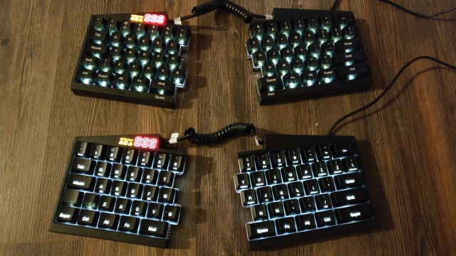
Backlit UHK prototypes in daylight

Backlit UHK 60 v1 prototypes in daylight

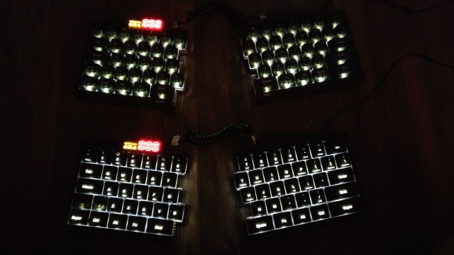
Backlit UHK prototypes at night

Backlit UHK 60 v1 prototypes at night

In the above pictures, the top UHK 60 v1 features opaque keycaps and the bottom has backlight friendly keycaps. Please note that these pictures are a bit misleading because in real life the brightness of the opaque keycaps is much dimmer than of the backlit keycaps. It's also worth noting that the final backlighting will be better. We'll optimize the placement of symbols for more even light distribution and carefully choose the best LED. The most important takeaway is that opaque keycaps may suit some, but probably aren't a great choice for most.

In order to make your UHK 60 v1 backlit right away, you can purchase a number of LEDs and solder them to the PCBs. You will have to use 3mm (T-1) LEDs. Be careful to choose a LED type whose rim is not larger than the lens itself, otherwise the LEDs won't fit into the keyswitches. Also make sure to use single color LEDs as bicolor LEDs won't work well. You can pick any LED color but LEDs of the same forward voltage should be used, otherwise ghosting may occur. Fear not, we'll provide detailed instructions for soldering.

Alternatively, you can wait for our backlight upgrade kit that we'll release later. The backlight upgrade kit will contain white LEDs and a backlight friendly keycap set. In the beginning, we'll only provide US ANSI and ISO versions.

As for the release dates, we're really not sure yet. We'll probably release the backlit UHK 60 v1 version and the backlight upgrade kit about a year after delivering the first batch. We're also unsure about the price but it will be reasonable compared to the price of the UHK 60 v1.

It's worth mentioning that although backlighting is a nice feature, the labels of non-backlit keycaps are easier to see in daylight.

Multiple brightness settings will be provided. One is a global brightness setting of 100 levels that affects every LED including both the LED display and the LEDs beneath the keycaps. The other is a per-key brightness setting of 256 levels which will enable us to do all kinds of fancy animations. This per-LED brightness setting can also be applied to the LED display as a whole. The formula is: actual brightness level = global brightness * per-LED brightness.

We plan to implement RGB backlighting eventually but surely not anytime soon, as it will require a complete redesign of the PCBs.

We also got a question about whether it's possible to solder only a couple of LEDs, for example only the LEDs of the home row. While it is possible, it will likely cause ghosting issues when using different per-key brightness values. This problem can be solved by telling the LED drivers which LEDs are actually present. We can implement a related user interface in Agent to mark individual LEDs populated/unpopulated, but we will only do so if there will be enough interest for this seemingly special use case.

Lastly, I'd like to note that while backlighting is clearly a neat feature, it's not necessarily better than not having backlighting. In broad daylight, the letters of the opaque keycaps are easier to see than the labels of the backlit keycaps. This is also true when the backlighting is off and simply backlit-friendly keycaps are used due to their material.

So this is it! Hopefully, all your questions are answered now. If not, please ask away in the comments. Have a beautiful weekend!
Hello and welcome to this month’s UHK update!

TL;DR: Our most recent prototypes have successfully passed EMC pre-compliance testing. The final certification will be taking place in June and is expected to take 4-5 weeks which will push delivery to July. Manufacturing is proceeding apace. One of our prototypes has became a movie star.

You can always check out the expected delivery date and update your shipping address on your Crowd Supply account page.

EMC pre-testing

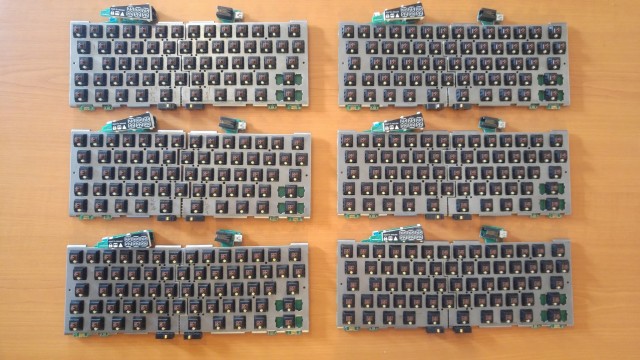
Not long after our previous update, we assembled 6 prototypes for the upcoming EMC pre-compliance measurement. These are v7.2 prototypes featuring EMC redesigns and related extra components, such as a ferrite choke.

Six UHK prototypes

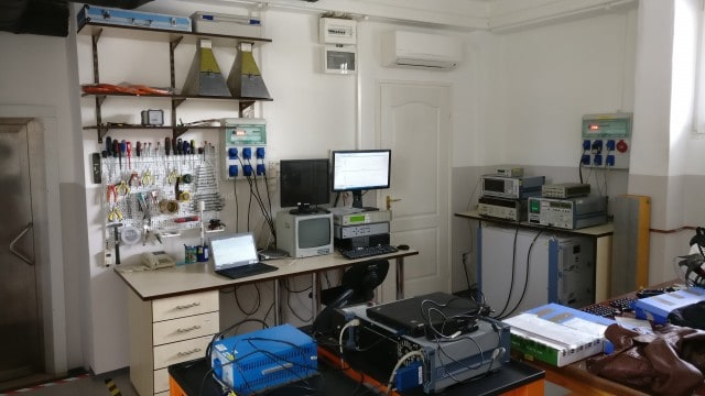
This time, instead of going to T-Network, we went to TÜV which was a much better experience. Their control room is more modern and tidier.

Measurement room

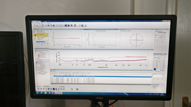
They use a more sophisticated measurement software.

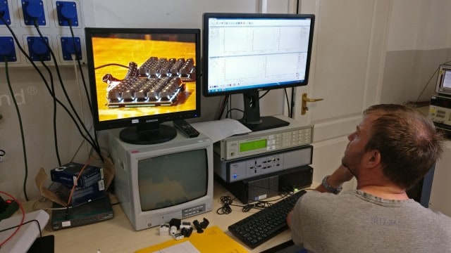
Measurement software

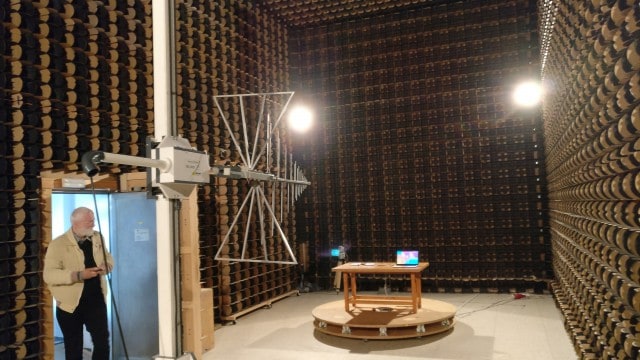
Their measurement chamber is more spacious.

Measurement chamber

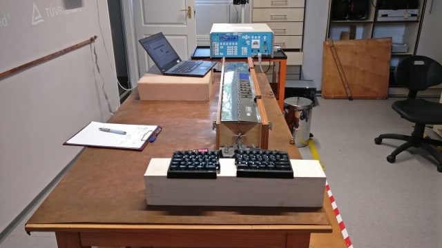
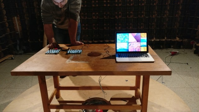
We told you the last time that the laptop we brought didn’t pass the test in itself, so we’ve made sure to bring a MacBook Pro this time to avoid such problems.

Measurement chamber table

Please note that the we don’t provide a backlit UHK yet, but the prototype exists

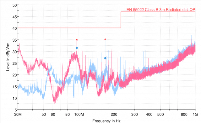
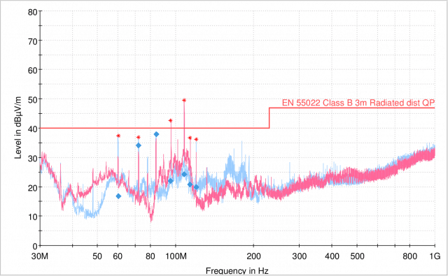
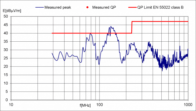
The measurements taken by TÜV are of considerably higher resolution than those at T-Network, and they do take proportionally more time. Instead of taking around 3 minutes, they take about 15 minutes each. This time, we passed the test! You can see the result below.

EMC measurement

This may look like a fail, but it's not! There are two peaks that are above the safety zone, but as it turns out, there are two measurements involved. In the first measurement, the peaks get detected. In the second, the peaks are more closely investigated which usually results in considerably lower values. The final values are marked with blue rectangles below the peaks, and they're all within the safety zone.

This is clearly a much better result than anything we’ve ever measured, although admittedly, the safety margin is quite tight around 84 Mhz. Endre has an idea how to make it even better by replacing some components, and we’ll test his idea in a week, but we’ve already booked a certification date for June regardless.

We’ll send two final prototypes to TÜV Hungary by the end of May, who will in turn forward the prototypes to TÜV Netherlands where the actual certification will take place. The certification itself is expected to take 4-5 weeks. This is longer than anticipated and the PCBs can only be mass produced after the certification succeeds. Unfortunately, this pushes delivery to July.

Manufacturing news

Let’s see some major news from the manufacturing department:

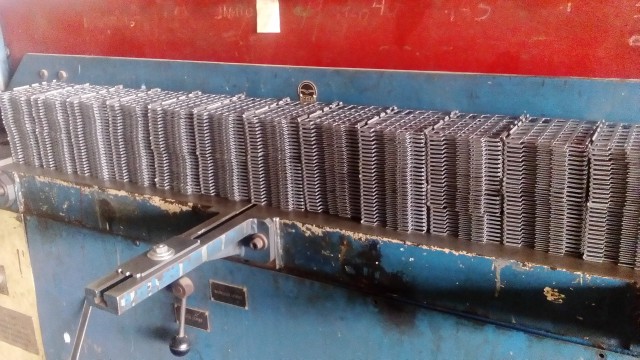
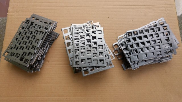
  • 1,000 steel plates have been manufactured and 3,000 more are in the works. Placement of the switches into the plates will begin soon.

1,000 plates manufactured

  • A pilot run of 100 pairs of the wooden palm rest parts have been ordered, and 900 pairs are set to follow.
  • The testing of the modified injection molding tools will take place in a week.

One of our prototypes has became a movie star

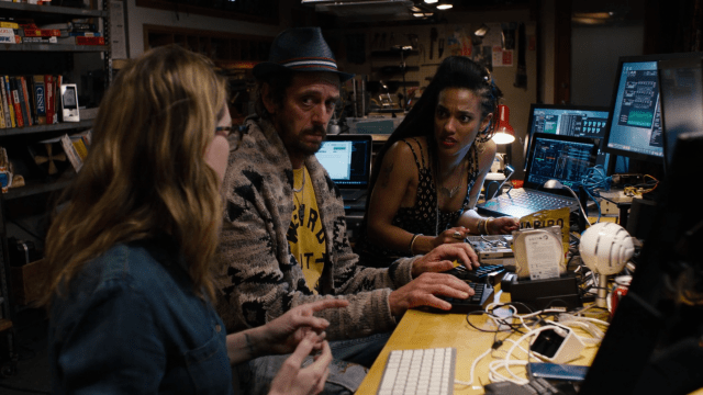
About a year ago, the assistant propmaster of Netflix series Sense8 got in touch with us. She told us that there’ll be a hacking scene in the series, and asked us whether we could provide a prototype to be filmed. Of course, we said yes in a heartbeat. Fast forward one year, we got featured in the series!

UHK in Sense8

You can see the UHK prototype in:

  • S2E03 (Obligate Mutualisms): 20:02 (-31:13)
  • S2E04 (Polyphony): 2:11 (-55:56) multiple cuts in 10 seconds, 5:01 (-53:06)

And a couple more spots here and there. You’re welcome to let us know if you notice another scene.

Needless to say, we’re thrilled to be featured. Thank you so much for the opportunity, Netflix!

This wraps up our May update, Ladies and Gentlemen. A lot of things are happening in parallel as usual, and with the certification of the PCBs on the horizon, we’re really getting close.

As always, we’ll be keeping you updated on a weekly basis on social media, and on a monthly basis in this blog and our newsletter.

Talk to you on 2017-06-15!

Hello again and welcome to this month’s UHK update!

TL;DR: We’re inching towards mass production. We’ve received tons of parts from our suppliers. The design of the palm rest is finalized, and our new PCBs are being fabricated.

Our delivery date is unchanged, which you can always check out on your Crowd Supply account page.

Now let’s delve into the nitty-gritty!

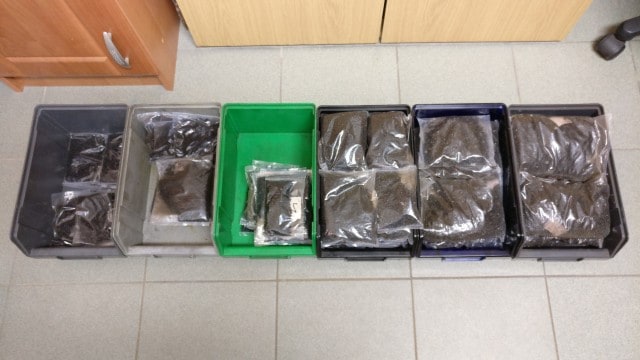
Big boxes galore

Not long after the previous update, a van arrived, chock full of goodies.

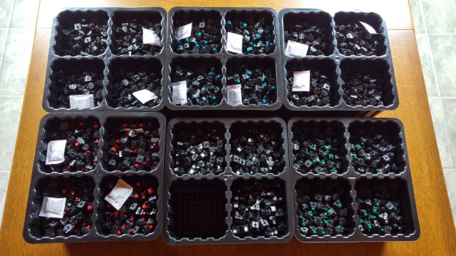
The majority of the boxes contain switches. Lots of them. 127,000 to be exact.

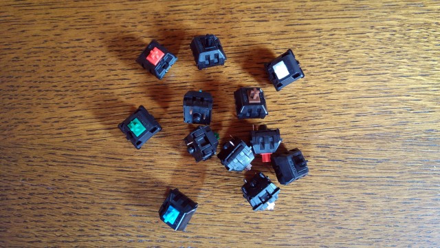
You can see all the 6 switch types including brown, blue, red, black, clear, and green.

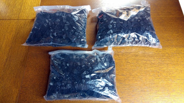
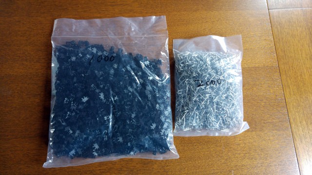
A fair number of boxes contain 131,000 keycaps. A single bag contains 1,000 keycaps of the same type.

Yet another box contains 11,000 stabilizers and 5,500 stabilizer wires. Assembling these little guys will be quite an exercise.

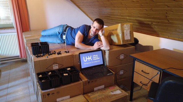
When seeing all the boxes neatly arranged, I couldn’t help myself, so I posted the following picture on April 1st.

You guys totally got it by immediately replying with the (in)famous 1970’s Bill Gates centerfold on social media. Well done!

Small bits and pieces

In the shipments were plenty of smaller parts, too. Let’s see what we’ve received.

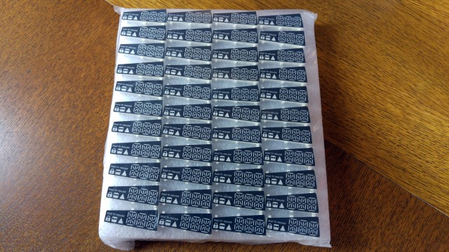
A small sample of the nearly 2,000 LED displays

10,000 pogo pins

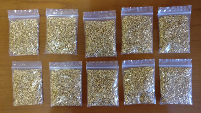
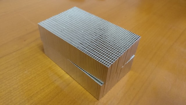
2,000 neodymium magnets

As a matter of fact, we’ve received another block of 2,000 magnets, but we didn’t dare to put the two blocks close to each other. The combined force of these magnets is formidable, which could have shattered the magnets, or even worse, our hands.

Final palm rest design

A while back, we showed you a palm rest version we thought was very close to final. Boy, were we wrong. As it turned out, the milled aluminium base plate had a tendency to bend a little bit when the legs were flipped out and force was exerted on the palm rest. András was looking into alternative design and came up with something we’re very proud of.

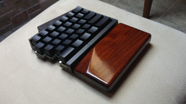
Now, we’re using a steel baseplate to connect the wooden part of the palmrest to the keyboard. This results in a stronger connection, making flexing a non-issue. As you can see, a recess was designed right where your thumb resides, which will make it easier to press the thumb button. We think it’s quite a useful feature.

The wood is more emphasized in this design, resulting in a classy minimalism. We plan to choose graphite color instead of the current brown color. We believe it will look just as beautiful as brown, and it will gel better with the black color of the keyboard.

We’re waiting for yet another sample, then we’ll pick a manufacturer, and launch the mass production of the palm rests.

Redesigned PCBs

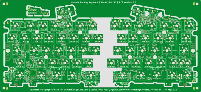
In our last update, we let you know about the EMC test results of the v7.1 UHK PCBs which were a lot better than v7.0, but still not good enough. Since then, we’ve finished the design of the v7.2 UHK PCBs.

The PCBs were redesigned by István based on Endre’s suggestions to reduce EMC emissions. Right now, they’re being fabricated, and should arrive soon. As soon as they arrive, we’ll assemble a half dozen prototypes and head to the EMC lab.

Speaking of the lab, instead of going to T-Network, we’ll go directly to TÜV from this point on. I recently contacted TÜV, and realized that they also do EMC pre-testing for a reasonable price. Even better, they will do the final EMC testing and issue the certifications, so it’s better to familiarize them with the UHK as soon as possible.

On the assembly front, we’ve just ordered electrical screwdrivers, screw dispensers, a glue dispenser, and a number of jigs are being made to speed up mass production.

A lots of further progress is expected soon. We’ll get 2,000 metal plates manufactured in the upcoming days, and the mold is almost fully ready, too, making it possible to manufacture the cases very soon.

In our true style, we’ll keep you updated on a weekly basis on social media, and on a monthly basis in these newsletters.

Talk to you on 2017-05-18!

Hello, and welcome to this month’s UHK update!

TL;DR: Our most recent EMC test results are much better than the previous results, but they’re still not good enough. We’re working hard on our new prototype to pass the tests, but this delays the project by about a month. Lots of progress is happening on other fronts, too. Please read on!

Parts are flowing in

The UHK contains loads of components, and some critical ones are flowing in one by one. These are the most recent parts:

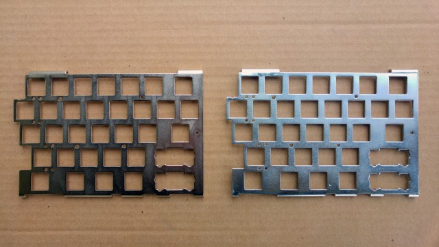
100 ANSI left, 100 ISO left, and 100 right plates have been manufactured so far. These plates will be used for the first production run. Of those plates, we have 20 of each in hand to check their quality and accuracy.

These 2 plates were surface treated with Nickel and Zinc.

There are also loads of smaller components that arrived lately:

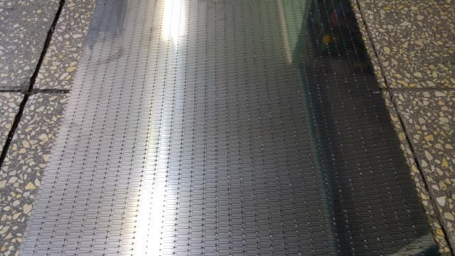
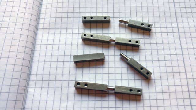
4,000 magnet counterparts laser-cut

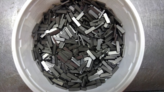
A couple magnet counterparts after grinding

140,000 screws

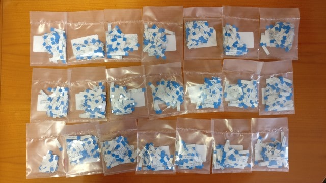
2,100 FFC cables

We’ve already ordered the switches, keycaps, keycap stabilizers, and displays which are expected to arrive soon.

The manufacturing of the guides and magnet counterparts is in progress. These are multi-step manufacturing processes, and they’re well underway.

The state of the molds

Currently, the molds are being tweaked, and the tweaks are mostly cosmetic by nature. All things considered, they’re already in very good shape.

András showed the current case samples to one of his friends recently, who works for a contractor of a premium car manufacturer, and his friend was genuinely impressed by the quality of the case, so we’re already doing pretty well.

Apart from the cosmetic fixes, we also plan to add one or two snap fits to make the case more rigid when the palm rest is attached to it. These modifications won’t affect our schedule.

EMC testing, 2nd round

Here we go again. Since our last update, we’ve created new prototypes to be tested in the EMC lab.

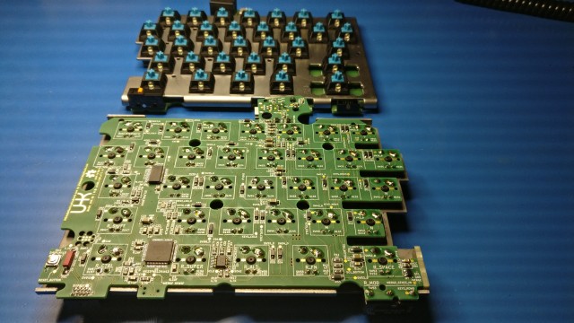
These are actually two right keyboard halves. The left keyboard half hasn’t been redesigned because, according to our tests, the USB is the major culprit when it comes to EMC issues, which are located on the right half.

We were told that a 4-layer PCB should perform better when it comes to emissions than a 2-layer one, so I decided that we should create both a 2-layer and a 4-layer PCB and see how they stack up.

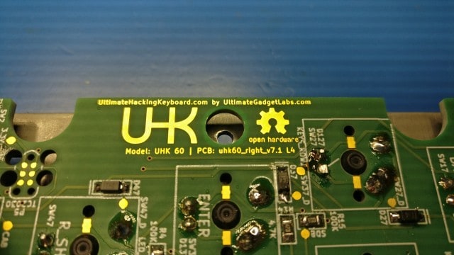
The naked eye can hardly tell the 2-layer and the 4-layer PCBs apart, so I put an “L4” identifier right after the PCB identifier text for the 4-layer PCB. Now it’s easy to tell.

Even though my hopes were high that we’d pass the tests with the new boards, I prepared for the worst and was looking for expert help. That’s how I found Endre Köcze.

Endre has a lot of experience behind him as an electronics engineer, and he’s a pleasure to work with. He has taken a thorough look at the UHK design, and we went to the EMC test together.

The test results started off as quite a surprise. First, we measured only the laptop as a reference point, and according to the measurements, it didn’t pass! Go figure.

Previously, we used Robi’s laptop, which passed the test with flying colors. This, however, was Anna’s, my wife’s laptop. Admittedly, this laptop is not as fancy as Robi’s laptop, but a reputable manufacturer makes it, and it should also pass the test.

The first takeaway is that we’ll bring as many laptops as we can next time, pick the least heavily emitting one, and use it in further measurements.

Next, we put the laptop under the measurement table, and then its measured emission got just below the red line. But when we added a shielded USB cable, even with the ferrite on the host end, it went just above the limit. This is clearly not ideal, but this is the best we could do on the spot. The measurements are still useful, and we’ll use a better laptop next time.

In this setup, the UHK was on the table, which is the center of measurement towards which the antenna points. Being under the table, the laptop didn’t affect the measurements so much. Next time, we’ll probably use a 5-meter-long USB cable and put the laptop as far as possible.

Around the end of the measurement, the OS shut down because the battery was so low. We could still use the laptop without the OS running, but both the low battery state and the fact that no OS was running might have affected the last four measurements. The lesson here is obvious: Power the laptop from a damn charger! And on that note, we’ll probably put the charger as far from the center of the measurement as possible, too, and use an extension cord to power it.

As for the actual UHK measurements, the results are very promising. The measurements of the 2-layer PCB were no more than 4 dB above the limit and no more than 7 dB above the limit with the 4-layer PCB. This is very promising compared to the first round of measurements for which even 16 and 18 dB above-the-limit values were measured.

Endre has a concrete plan regarding the redesign of the PCBs. He’d like to add a common mode choke and ferrite beads at strategic places, and István is ready to redesign the boards accordingly.

In addition to the changes mentioned above, I plan to implement a number of firmware test features so that we’ll be able to narrow down the cause of various spikes. I think of features like disabling I2C / USB / backlighting and adjusting the clock speed of the MCU with dedicated keys on the keyboard.

I think that with all the above test procedures, test modes, and redesigns in place, we shall defeat the EMC issues with the next prototype, which should be ready in a month.

Due to the EMC hurdles, we must delay delivery by a month. This is frustrating but very much necessary to make the UHK happen. We’re working as hard as we can to hit it soon.

In our true style, we’ll be keeping you up-to-date in our weekly social media updates and monthly newsletters. Thank you for tuning in, and talk to you on 2017-04-13.

Hey there! It’s February, and we have a new UHK update for you. A lot has been happening, and, barring unforeseen delays, we’re on track for April keyboard delivery. Let’s delve into the gory details!

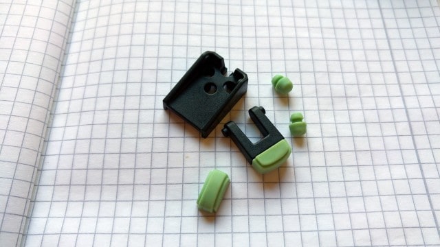
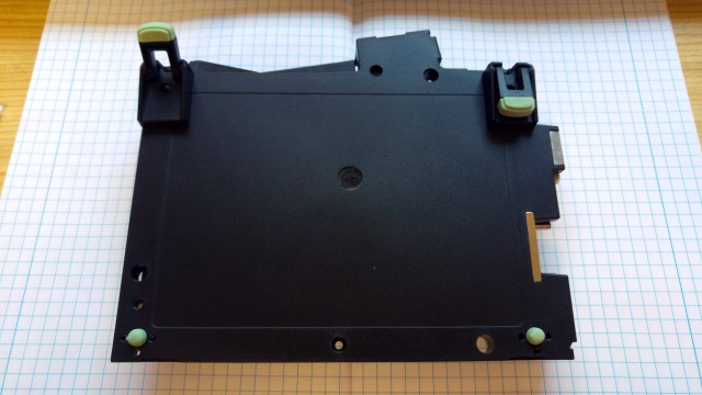
Rubber feet and caps

There are small rubber feet and rubber caps on the ends of the flip-out feet of the UHK. Up until this point, we only had 3D printed versions of these caps, but the tooling has finally been created for them, so we got a couple samples.

Rubber samples

Rubber samples. The final rubber parts will be black.

Feet mounted

Feet mounted

The samples are surprisingly good for a first run. There’s only a very slight modification to be done to the tool to make it fit perfectly, which will completely eliminate the parting lines that are now slightly visible.

Steel guides

The steel guides are currently being manufactured. Here are some samples before vibration grinding them.

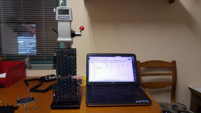
Force measurements

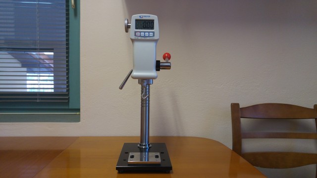
András has made a number of measurements with our new force measurement gauge.

To find the optimal pull force between the keyboard halves, András has made measurements using various magnets. They must not be too strong, but strong enough to prevent the accidental separation of the halves while carrying or during a fall. Some final tests still have to be made in the coming days, then the chosen magnets will be ordered.

Right-half bootloader completed

Even though the bootloader for the right keyboard half was already working, it wasn’t secured. That means that if we transferred a firmware image whose memory region overlapped with the bootloader memory region, the bootloader would have been overwritten by the firmware image.

Luckily, Kinetis devices offer hardware level memory region protection for such cases, which Santiago made a good use of. Now, with the memory protection in place, even if the bootloader would want to overwrite itself, it couldn’t.

But this isn’t the only safety measure that KBOOT, the Kinetis bootloader, provides. Let’s say that the firmware transfer gets aborted due to a power outage or for whatever reason. In such a case, the CRC checksum of the firmware doesn’t get updated and when plugging in the UHK the next time, KBOOT detects the CRC mismatch, and instead of jumping to the corrupted firmware, it stays active, waiting for a new, valid firmware transfer.

With the above protections in place, we believe that the right keyboard half is unbrickable via USB. I’m delighted that NXP offers such a comprehensive bootloader. It makes things so much easier and safer.

Santiago will make the bootloader for the left keyboard half work, too, but there’s something else to be done before then.

Firmware progress

The UHK firmware has already been working for quite some time, but some things weren’t exactly rock solid and optimized. This is about to change.

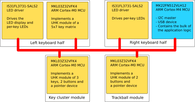
The reliable and resilient communication of the UHK parts is the core concern. If you think of the left and right keyboard halves, and the left and right modules, these are all separate computers, and some of them contain multiple processors. The bus via which they’re interconnected offers a limited (although sufficient) bandwidth which must be utilized as efficiently as possible. To make things even more complex, any module can be disconnected, or connected any time, so hot-plugging must be seamlessly handled.

The main I2C bus of the UHK

First up, the communication should be made fully asynchronous. Synchronous communication was easy to implement because it’s just a sequence of instructions, but it’s highly suboptimal because it uses inefficient busy loops instead of interrupt handlers, and it’s hard to do robust error handling with it.

I was aware of these problems from the get-go, but I wasn’t concerned because I wanted to implement a working firmware as quickly as possible and improve it later. Now that we’re marching towards release, it’s time to solve these problems properly.

When changing sync code to async, the application logic changes quite a bit because instead of using a sequence of sync calls, an async callback gets fired whenever a communication event occurs, and a state machine has to be implemented inside of the callback.

I will end up implementing a scheduler state machine, so that the I2C master (the blue rectangle in the diagram above) will talk to I2C slaves (yellow rectangles) in a round-robin fashion. The purpose of these inter-module messages is to propagate state between the modules.

This will result in a very clear programming model in which the scheduler will sync the state of the modules in the background all the time, and the rest of the application logic of the master will be able to deal with the various module-specific data structures as if they were local.

I recently hit a related problem that I was unable to resolve, so in my true style, I summoned Santiago. The problem was that communication did not resume between the halves when I disconnected then reconnected them, even despite using async I2C calls. Santiago looked into the issue and concluded that the KSDK I2C driver is not very robust.

As it turns out, I2C drivers typically assume that I2C devices don’t get hot plugged, but are permanently soldered onto a PCB. Obviously, our situation is different, which calls for a more robust I2C driver on which Santiago is working right now.

PCB redesign

In our previous update, we told you that the UHK prototype has failed the EMC test and that I will find a professional PCB designer who (unlike me) does know what he’s doing.

I’m happy to introduce István Pánti, PCB designer extraordinaire!

István Pánti

István has been using Altium Designer over the years, a commercial PCB designer application which happens to be the number one industry standard worldwide. Luckily, he was willing, and even excited to learn KiCad, and according to his opinion it’s a surprisingly powerful tool for a Free Software package.

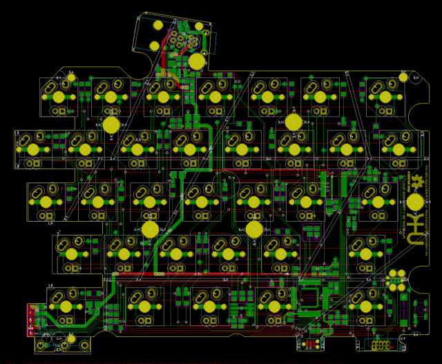
Then he cleaned up all of my traces and most components of the right UHK board, and started to reroute the tracks, beginning with the D+, D- differential pairs of USB, which are supposed to be the most problematic according to the EMC test measurements. His design turned out to be a lot cleaner than mine.

The redesigned right side PCB

The redesigned right side PCB

Routing PCBs is not black magic, but it may seem like it to the outsider, especially when dealing with EMC issues. There are a lot of layout rules to follow. Lucky for us, István has routed his fair share of PCBs before, including a USB hub, and read plenty of USB PCB design guidelines which now he puts to good use.

He’s been making great progress recently, and the end of the redesign is near. You can see his progress on GitHub.

I asked him to also create a 4 layer version of the PCBs after he finishes with the 2 layer version. Then we’ll prototype both versions and put them to the test. The 4 layer PCB should perform significantly better in the EMC department, but we’ll only pick it if necessary because it’s also significantly more expensive. This way, we can progress as quickly as possible.

Manufacturing progress

A short overview:

  • 2,000 LED displays are being manufactured.
  • 16,000 steel guides are being manufactured.
  • 4,000 magnet counterparts are being manufactured.
  • 2,000 FFC cables are being manufactured.
  • We will order 10,000 pogo pins, 126,000 keyswitches, and 126,000 keycaps in a few days.
  • 140,000 screws are on their way to us.

Lots of stuff are about to flow in pretty soon. Expect pictures of big boxes filled with goodies!

Thank you for reading the February installment of UHKzine. Talk to you on 2017-03-16!

Happy New Year, everybody! This is the most recent installment of UHKzine - your authentic, monthly news source on all things UHK. In this update, there’s good news (production is moving along nicely), bad news (we need to delay delivery by two months to April 2017 in order to fix electrical noise so the UHK can pass FCC and CE certification), and more good news (we’re already vetting some great candidates to fix our PCB design in order to reduce the electrical noise).

The first sample PCB batch

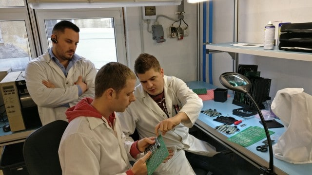
We visited our PCBA contract manufacturer to prepare for mass production. They wanted to assemble five boards, so that we can get a good grip on the process, create jigs, and optimize for manufacturing as much as possible.

First, we figured out how to solder the switches and plates to the board in the most productive manner.

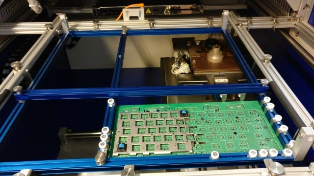
After discussing the surface mount part, we talked about through hole assembly. The panels will go into the following jig.

And the jig will go into the selective wave soldering machine, soldering the leads of through-hole components, mostly the keyswitches.

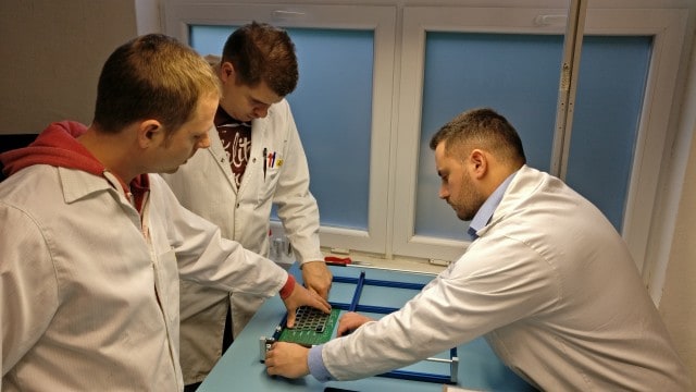
Some time after the meeting, they sent us a couple of pictures of the assembly process.

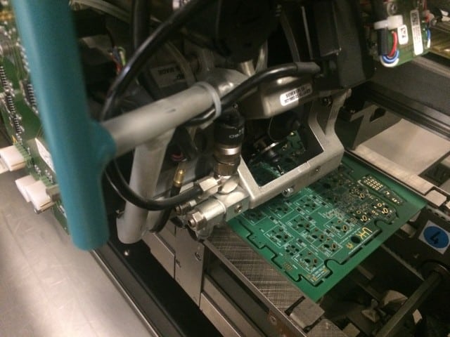
UHK panel in the pick and place machine

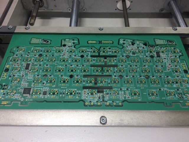
SMT-assembled panel

Soldering the switches

After finishing with the first sample batch, our contractor has followed up with some suggestions to further improve the PCB design for manufacturing. These were very minor improvements. Things are looking good in this department.

New case and plate samples

We’ve got a couple of new case and plate samples from our contractor.

Bottom case parts and plates

Top and bottom case parts and plates

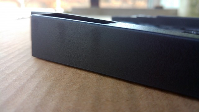
The new plates are extremely accurate and fully ready for production. The cases are close to perfect, but still have some sink marks.

Top sink marks

Side sink marks

We’re about to use the mold with a more capable injection molding machine, which may make these sink marks disappear. If not, we’ll modify the mold further.

Parts are flowing in

We’re in the process of ordering every part from all around the world. Some recent ones:

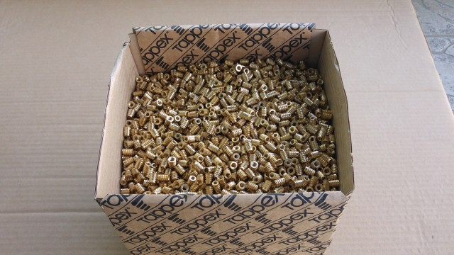
Threaded inserts

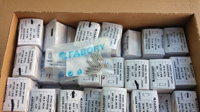
Dowel pins for the male guides

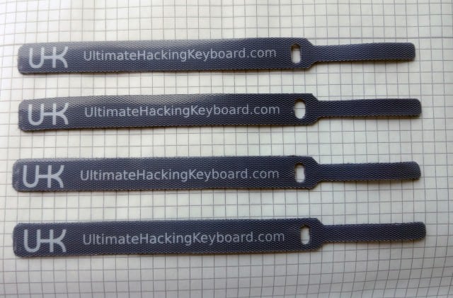
USB velcro ties

We’ll be keeping you posted on the new items as they arrive.

Measure the force, Luke

The splitting / merging of the keyboard halves is a central part of the UHK user experience. This experience is very much dependent on the force the magnets exert. Although we have an intuitive feeling regarding the optimal amount force, being engineers, we want to be able to measure it, and make sure that it’s consistent across the keyboard halves, and across a keyboard half and module. This has justified having a force gauge.

The measurements will give us a good idea about the strength of the magnets and how to choose the material of the magnets’ counterparts. We’re only a couple of days away from starting the production of the counterparts, and ordering the magnets.

EMC testing

EMC stands for electromagnetic compatibility, and such tests basically make sure that electronic devices do not interfere with each other. Because, believe it or not, people expect their phones to work when the microwave is on. You get the idea.

The UHK is no microwave, but in order to be allowed to be sold worldwide, we have to stick FCC and CE logos onto its back. And in order to be entitled to use these logos, the UHK must pass standard EMC tests.

This made us visit the EMC lab of T-Network to measure the electromagnetic emission of the latest UHK prototype. T-Network is a logical first step because their measurements are fairly affordable unlike the final measurements and certification at TÜV which is an order of magnitude more expensive. We better get this right because if not, we’ll have to pay big bucks to TÜV upon every subsequent try.

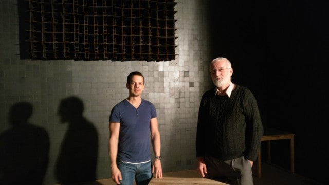
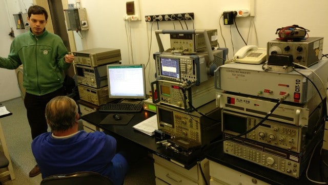
After walking into their building, making a few turns, and finding the right door of the long corridor, it wasn’t hard to notice that we arrived to the right place.

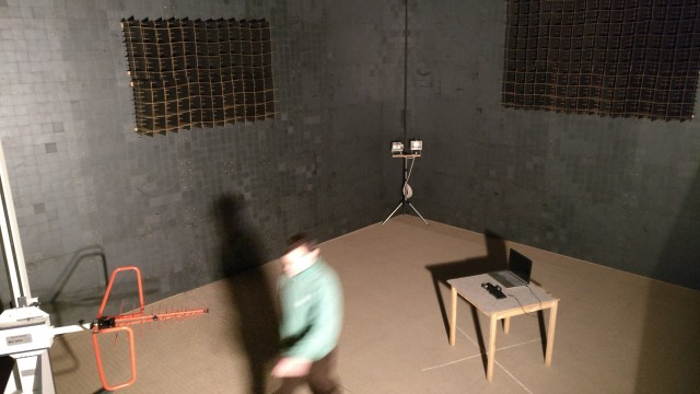
When opening the inner door of the lab, the SAR, or semianechoic room gets revealed. This is where the actual measurements take place.

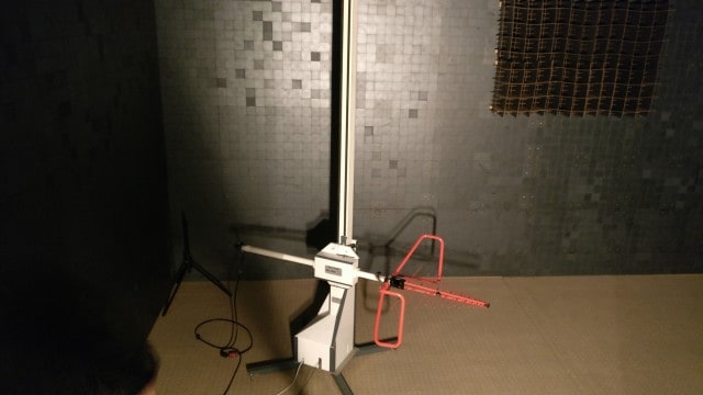
In this setup, the UHK is plugged into a laptop and sits on a table, measured by the scary bigass antenna in the corner. Let’s take a closer look at it.

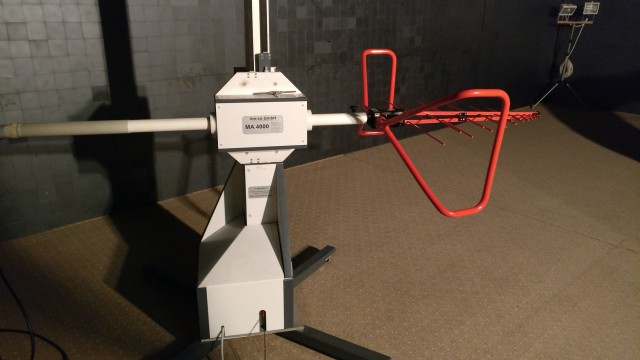
On this image, the antenna is oriented horizontally, and it stands in its lowest position, but it can rise way, way up.

During a measurement session, the antenna rises 4 meters upwards, then rotates its head vertically, and also does measurements that way. The result of the measurement is a graph.

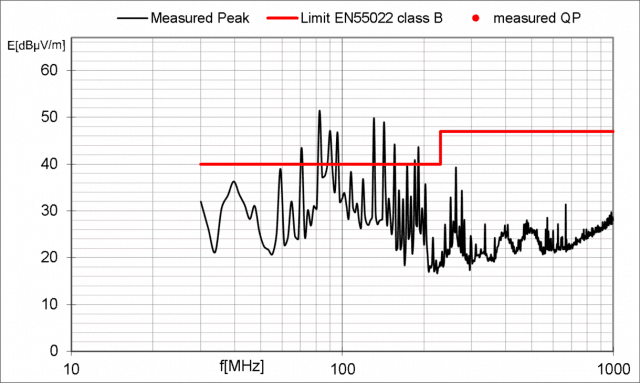
This one has failed

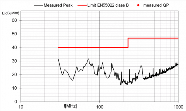
The goal is to stay below the red line which we only achieved once out of 15 measurements: when the UHK was powered from a USB power bank, and hence it only received power and USB communication was inactive.

Success!

So according to the measurements, we have a good reason to believe that the USB circuitry of the PCB is not routed optimally. Even though I couldn’t foresee this, it’s not all that surprising because I routed the PCB using some external help, and I’m not an electrical engineer.

I’ve been told that failing the first test is pretty usual, and we shouldn’t be overly worried. In any case, it’s apparent that the time has come for me to resign as a self-taught PCB designer, and hand over the redesign of the PCB to a professional. As a matter of fact, I may have already found the right person. More on him in the next update.

As a last word of this section, I’d like to sincerely thank Robi for helping so much in the lab. His help was critical to figure out the exact problem.

Introducing our new contributor

Free and Open Source software is known for attracting numerous contributions, and we’ve been fortunate enough to receive our fair share. Which brings me to Gergely, who is the king of the hill when it comes to keyboard firmwares.

My name is Gergely Nagy (or algernon, for those who don't speak Hungarian), and I'm a jack-of-all-trades kind of free software zealot. I first came across the UHK in late 2014 when I was looking for a new keyboard. Since that time, I ended up contributing to QMK (the firmware that powers my current keyboard), KeyboardioFirmware (which will power my next keyboard), and I couldn't help but contribute to UHK's firmware too, which will power my mother's next keyboard. I may have developed a thing for keyboard firmware, much to my wife's regret. My current focus is parsing the config sent by Agent, and teaching the firmware to apply that at run-time. ...and whatever else I can find the time for.

To this day, Gergely has been working on three entirely different keyboard firmwares, which unquestionably makes him one of the most knowledgeable contributors we can ever wish for. He’s been hard at work with the UHK firmware, and ended up implementing loads of features, including mouse keys and, most importantly, a significant chunk of the configuration parser. And it looks like he still hasn’t had enough!

Our deepest gratitude, and a UHK with all the bells and whistles goes to Gergely!

At the same time, Jozsi was working on Agent, making it able to transfer the selected layer to the UHK via USB. Seeing the configuration getting effortlessly updated in a blink of an eye via USB is magical. It’s very nice that all of our hard work pays off.

Expected delivery schedule

We keep making rapid progress and most things proceed according to our schedule, but not everything. The EMC issue is something we couldn’t foresee, and the PCB redesign will affect our delivery schedule.

We’ll try to reduce the delay as much as possible. Recently, I’ve made contact with expert PCB designers to resolve these issues as quickly as possible. I’ll meet all of them within days, and wrap this up as quickly as we can.

According to the above, we are moving the release schedule of the UHK and palm rest to the end of April. We wish we could do it sooner, but as a startup, we are destined to go through these hoops, and learn things the hard way. After releasing the first UHK model, creating further products is going to be so much easier!

As always, we will be keeping you updated on a monthly basis in our newsletter/blog, and on a weekly basis on social media. Should you have any questions, you’re always welcome to reach us.

Thank you for your continued support, and we’re excited to talk to you on 2017-02-16.

Hi there, and welcome to our monthly status update! Let’s warm up, and see what’s been happening in UHK land these days.

Mold meetup

Our mold-making contractor let us know that they’re done with the molds of every plastic part, so we made a second trip to Serbia to check them out.

The best part of the meeting was snapping together the top and bottom parts of the case, and hearing the satisfying click sound, meaning that the parts fit together accurately. This is not something we’ve ever heard when trying our 3D printed prototypes.

Putting the LED display into the case was a similarly elevating experience. These parts are so precisely fabricated that they look like a single part from the outside.

The newly created top case parts

The assembled case without the switches and PCB

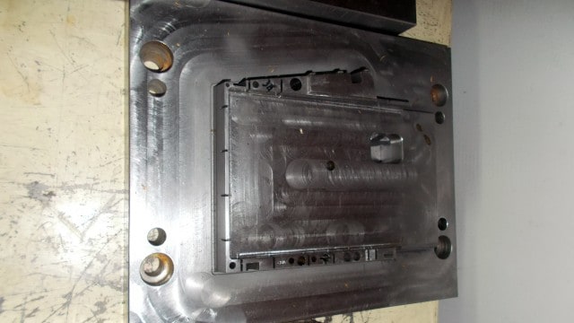
Having all of the plastic parts injection molded is a major milestone, but it’s not the end of the story. Aesthetics will improve by tweaking technological parameters of the molding process. This is fully expected in the world of manufacturing, and our contractor is working on them.

Inserts

Having the injection molded parts and the final inserts in his hands, András put the inserts into the case and tested them.

As it turns out, even 16 kg can't pull a single insert out. We're about to order 16K of these little guys.

Guides

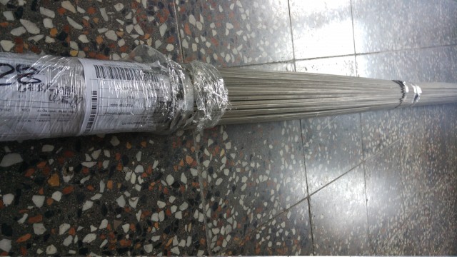
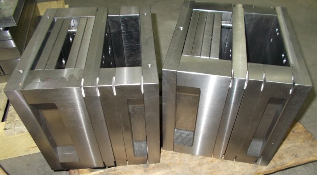
What does one do with 80 kg of stainless steel rods? Turn them into 16,000 guides to hold the keyboard halves together!

As you can see, we have already ordered the raw material, and we’ve also found a local manufacturer who will get the job done.

Palm rests

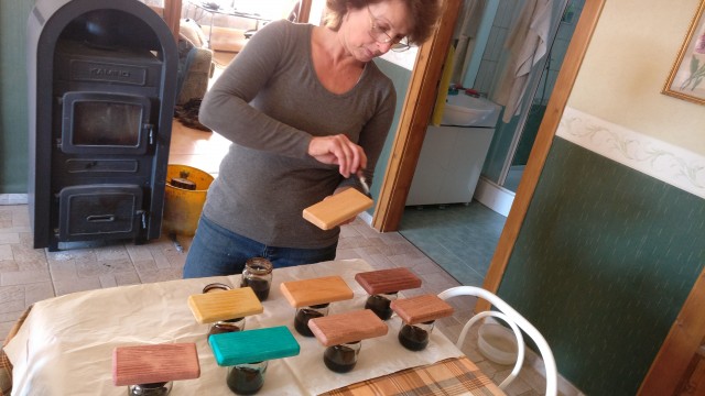
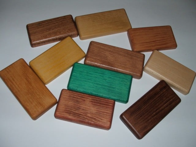
In our previous update, we published a picture of the wooden inlays on the palm rest but weren’t sure about the final color. Now, we’re experimenting with a couple of options.

Let me introduce you my mother, Klára Monda, who just happens to be a furniture painter folk artist. That’s right folks, the UHK is becoming a family business! Having more than 40 years of experience behind her, she’s more than qualified to dye and lacquer the wooden parts of the palm rests.

So far, a dark brown “walnut” dye seems to be the best match for the UHK case, but we will also give a graphite color a try soon. We’ll keep you posted.

New PCB

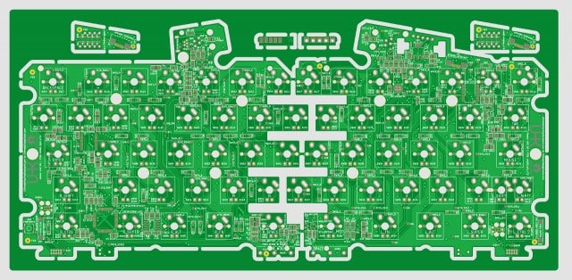
10 of our 7th generation PCBs are being fabricated at Eurocircuits and will arrive at any moment.

These PCBs should fully resolve acoustic and electrical noise issues and contain lots of small improvements. They’re heavily optimized for manufacturing, boast 100% test point coverage, and also include little touches like the UHK and OSHW logos. As soon as they arrive, I will assemble a couple and meet Robi to test them thoroughly.

5 of the prototype PCBs will directly go to our PCBA contractor. They’re eager to do a first small prototype run so that they can create the tooling for efficient mass production.

Agent

Józsi and Nejc have been working very hard on Agent. As the fruits of their labor, Agent has become far more polished than ever before.

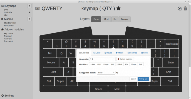
You’re welcome to check out Agent in your browser to see for yourself. Click on any key to see the key action popover appear. Then associate an action of your desire, and see the new action displayed on the key. Then rename a keymap, or its abbreviation, set it to default, duplicate it, or delete it. All these things should work smoothly now.

We still have a lot to do, but Agent already resembles the final application pretty well, and we’re making rapid progress.

All hail the Input Club

Jacob Alexander of the Input Club has been doing some mad science lately. He has created the The Comparative Guide to Mechanical Switches by doing one-of-a-kind mad science. Lucky for us, Kailh switches were rated among the top contenders, so it looks like we’ve made a great choice. We’re extremely impressed by Jacob’s work.

While speaking of the Input Club, let’s give credit where it belongs. When porting the UHK to ARM and searching for the best microcontroller and LED driver we could use, we checked out their open source keyboard designs, and picked the same ARM processor and LED driver that they used.

Later on, we upgraded to a more powerful processor of the same family, and created our own schematic, PCB, firmware, and configuration application, but still, they have definitely affected our design in positive ways, so mad props to them!

More frequent updates on social media

Lately, some of you asked for more frequent updates and we’re glad to comply! Since our last newsletter update, we published 3 updates on social media. The plan is to post updates on a weekly basis on social media. You’re welcome to subscribe to our Facebook, Twitter, and Google Plus channels to for even more UHK goodness.

And that was it, folks! We’ve arrived at the end of our December update.

Let me take the opportunity to wish every one of you Merry Christmas and a Happy New Year on behalf of the whole UHK team! We’re so happy that you guys are on board!

Talk to you on 2017-01-19.

Welcome to our monthly progress update! There is no shortage of news from this last month, so let’s go through them one by one!

Plastic case

We’ve already received samples of the bottom case parts, the buttons on the plastic case, and the top left and top right parts are well on their way. The following image is the top left part of the case with the sprue left on it.

Top left case sample

As it turns out, the ejector pins of the top left mold are unable to eject the part properly, so our contractor is in the process of adding an extra pin. We shall soon receive all the plastic parts of the case to evaluate them.

Palm rest

In the last update, we showed you the 3D printed prototypes of the palm rest. We also showed you foams of different types that could go into the palm rest. In the meantime, we’ve been thinking about using an alternative material to foam: wood.

Wood palm rests are considered to be the most premium solution. They’re nice to touch, pleasing to the eye, and last longer than foam palm rests. This is how our current palm rest prototype looks like.

Palm rest sample

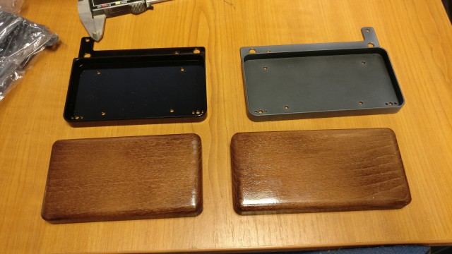
You can see the base plates of the palm rest on top. They’re milled out of solid aluminium, then anodized, and finally covered with lacquer. The left one was powder coated with glossy lacquer that did not change the black anodized color, and the right was covered with matte lacquer that changed the black anodized color quite a bit.

The current base plates feel extremely robust and look pretty nice, but to make them even nicer, we’re thinking about powder coating them black instead of anodizing them. This would result in a solid, semi-gloss, black color. We’ll give it a try later.

As for the wood parts, beech wood was used which got slightly dyed, and then a glossy lacquer layer was applied. The gloss is too much, so we plan to settle with semi-gloss lacquer, and we’ll probably end up using a darker brown paint.

LED display

The last time we updated you, we mentioned that our LED display was having ghosting issues. This was caused by the white LEDs whose forward voltage was significantly higher than the other red and yellow LEDs.

We haven’t found a viable solution regarding the white LEDs, so we ended up using yellow LEDs for the icons. This makes the charlieplexed LED matrix use only red and yellow LEDs whose forward voltage is similar.

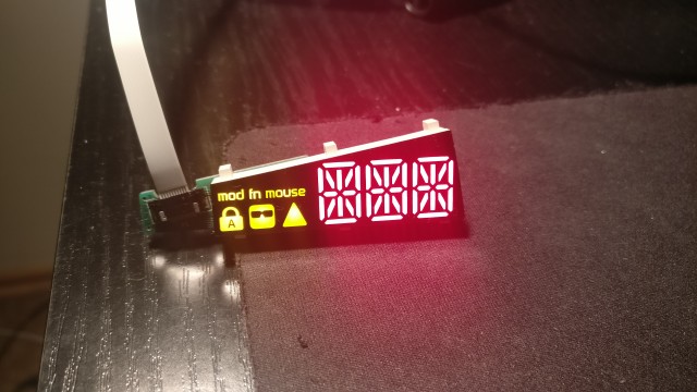
Yellow LED display

This simple fix has fully resolved the ghosting issue. Ghosts busted!

Bridge cable

One would think that the bridge cable is a no-brainer. After all, it’s just a simple spiral cable, so let’s just pick a random cable from any manufacturer and call it a day, right? As it turns out, that’s not exactly the case.

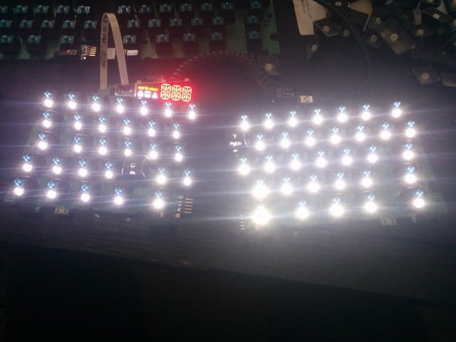
In the spirit of future-proofing the UHK for backlighting, I tested the bridge cable with all switch LEDs on to see whether it carries enough current to the LEDs.

UHK switch LEDs

It’s clear that the right half is brighter than left. When connected via the board-to-board connector, the brightness level evened out the halves. It became apparent that the voltage drop of the bridge cable was very high.

I figured out that there are two factors that affect this issue, which are the diameter and the material of the wires inside of the cable. My bridge cable was made of copper-clad steel instead of pure copper, which conducts electricity much better. As for the diameter, the wires of my cable were extremely thin.

I then started contacting spiral cable manufacturers to learn more details and find the best option. As it turns out, 24-30 AWG diameter wires can be crimped to RJ jacks, so I asked for 24, 26, 38, and 30 AWG copper cable samples.

After testing them, I could confirm that the resistance of these cables was much lower than my original cables, and lighting was even across the keyboard halves with any of them. In order to minimize the voltage drop, I wanted to pick the thickest 24 AWG cable.

That’s when the manufacturer warned me that 24 AWG cables may not retain their shape after stretching them moderately, which was an issue I was able to confirm. I figured that it’s the plastic exterior of these cables that provide the flexibility. There was too much copper in thicker cables, which made them not retain their shape after flexing. After testing the samples, I figured that 28 AWG and 30 AWG retained their shape well. So I picked the thicker 28 AWG one, and this will be our final cable.

Lesson of the story: not all cables are created equal, and the devil is in the details!

Electrical issues

The UHK will have to pass EMC tests so that we can stick FCC and CE logos on the back, allowing for worldwide distribution. Being aware of this issue, I knew the time had come to send one of our prototypes to an electrical engineer to be investigated from an EMC standpoint.

Luckily, a friend of mine, Robi, just happens to be an electrical engineer. He’s not even a mediocre engineer, but a great one, and he was very willing to take a peek at our prototype.

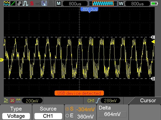
After receiving the prototype, Robi was eager to get his hands dirty. The first thing he did is hook his prototype up to a scope. The results were somewhat worrying.

Electrical noise before the fix

He told me that given this heavy electrical noise, there is not a fighting chance we’ll pass EMC tests.

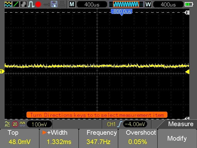
About 5 minutes later he told me that he had bad news and good news. The good news is that he managed to solve the electrical noise issue.

Electrical noise after fix

The bad news is that I wouldn’t like the solution.

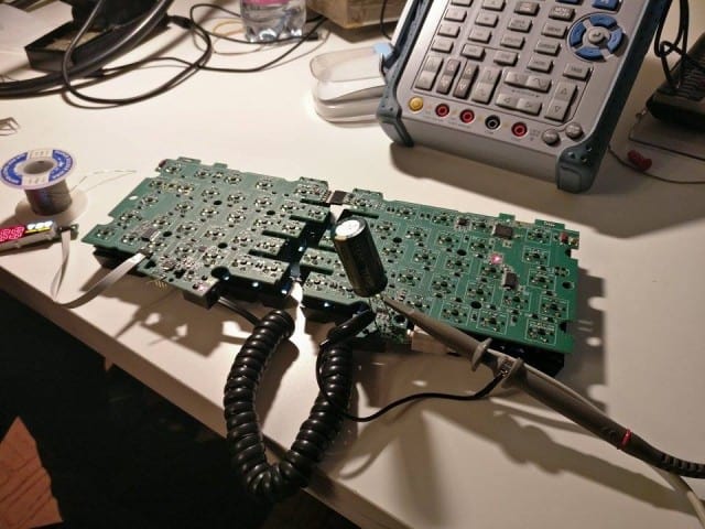
Huge capacitor on the PCB

The elephant in the room is the monstrous electrolytic capacitor soldered onto the PCB. If you’re afraid that it won’t fit inside of the UHK case, you guessed it right!

Luckily, using multiple SMD ceramic capacitors can provide sufficiently high capacitance. Robi also suggested using a ferrite bead and some extra capacitors near to the USB connector to further reduce electrical noise issues.

Acoustic noise

In the previous update, I mentioned that our PCBs were emitting some audible noise which was proportional with the number of LEDs enabled. Robi also looked into this issue and the solution has several steps to it.

First, throwing more capacitors onto the PCB drastically reduces electrical noise, which in turn also reduces the piezoelectric effect responsible for the audible noise.

Second, the ceramic capacitors will be placed in a way that they won’t enforce each other’s vibrating effect.

Third, we’ll use higher value resistors for the R_EXT pins of the LED drivers because the current consumed by our latest prototype with all LEDs enabled is higher than the maximum current the USB connection can provide. Lower current draw will translate to lower noise, and given the logarithmic sensitivity of the human eye, the brightness difference will hardly be noticeable. LED lifespan will also benefit from this change.

We’re fairly confident that the above fixes will resolve every electronic issue. Our next PCB should be ready to pass EMC tests!

Bootloader

Santiago has been extremely busy with his work at NXP (now Qualcomm). So much so that he’s had hardly any time for us, but luckily, he managed to spend a whole weekend on the bootloader recently. Because of his efforts, the master bootloader is working! This means that it’s now possible to update the firmware on the right keyboard half via USB.

But that’s only half of the story. The other half involves implementing the proxy which will route the firmware of left keyboard half and modules via the right keyboard half. If everything goes well, Santiago be able to allocate enough time to get this done soon.

Our new contributor

Robi

I briefly mentioned my friend, Róbert Csordás, above. He has been a huge help in solving the electrical issues of our design, so this is the part where we express our appreciation.

He hasn’t only helped with electrical issues, but also improved the firmware in a lot of ways. He implemented a QWERTY layout, then made the communication between the keyboard halves more robust.

Robi is already a full-time UHK user. His only wish is to receive a plastic case for his prototype, so that the bare solder joints of the PCB won’t scratch his desk. We’ll make sure to send him a final UHK with all the bells and whistles as soon as we can.

Thank you so much, Robi!

Project progress and schedule

Right now, the steel guides, the feet mold, the rubber mold, and the magnet counterparts are being manufactured.

The molds of the case and the steel plate cutting tool are being adjusted to meet our manufacturing constraints. This is planned, but it will take a little longer than expected.

The PCB is being redesigned as described above in order to minimize electronic and acoustic noise. It will be ready by the end of the upcoming week, and then we’ll put it through EMC tests in December. We should have the necessary certificates by that time. We’ll launch a prototype run for the PCBs in January and start our first full production batch in February.

By the time the boards get manufactured, we’ll have all the parts and packaging in our warehouse, ready to be assembled and shipped.

We can assure you that everything happens according to the grand plan, but many things take longer than expected. We know how much you would love to have a UHK by the holidays, and we’re doing everything we can to deliver as soon as possible, but we can’t reasonably expect to ship sooner than February.

We’ll keep these updates coming with clockwork accuracy, so you’ll be aware of our progress at all time. Should you have any questions, we’re always here for you.

Thank you for your continued support, and we’ll talk to you again on 2016-12-15.

You know the drill: a new month always brings a new status update. Let’s delve into what’s happened lately!

Tooling status

Our mold making contractor has been working on the top molds of the UHK case and are on schedule. Here are the molds of the top case parts:

The mold of the top left case part

Molds of the top case parts

At this pace, the end is near. We should be able to test the final plastic parts within weeks!

LED display

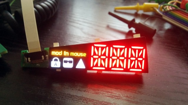
In our previous update, we showed you the mold for the LED display. Since then, our supplier baked a complete unit featuring the PCB, the LEDs, and the epoxy inside. The result is a blindingly bright LED display!

LED display shining bright

The display is so bright that it’s rather overkill at night. Luckily, the LED driver ICs that we use allow us to precisely set the brightness level - which we will expose as a user option eventually.

And this is how it looks when scrolling the alphabet on it:

Actually, it looks better in real life, but not when recorded with a mobile phone under suboptimal lighting conditions.

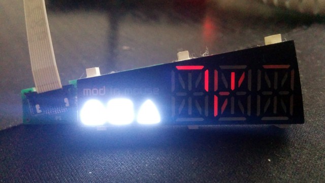
Some problems still have to be resolved, though. The forward voltage of the white LEDs are considerably higher than of the red/yellow LEDs which results in an unbalanced charlieplexed LED matrix that has a tendency of ghosting which is noticeable, especially when only the white LEDs are on:

LED display ghosting

There are several ways of fixing this issue, so if everything goes well we’ll simply throw a couple of diodes at the LED matrix and make our supplier redesign the PCB of the display. We really try to keep the white LEDs, but in the worst case scenario, we’ll use LEDs of a different color instead, whose forward voltage matches that of the red/yellow LEDs.

Another issue to be resolved is acoustic noise. The LED driver ICs generate a high frequency noise that is slightly disturbing. This is due to the capacitors and inductors, which shrink and expand according to the PWM signal that drives the LEDs. There are about a half dozen ways to deal with this issue. Some of them increase costs, others increase complexity. We may end up combining multiple approaches to get the best result.

Firmware

Lots of things have been happening in firmware land lately. The FRDM dev boards that feature the processors we use have already been working for a while, but the firmware wasn’t tailored to our PCBs.

First up, I tried to set up the multipurpose clock generator of the K22 MCU which made me realize how much of a hideous beast it is. It would have likely taken me weeks to make it work, so instead, I summoned Santiago who set it up like it was a walk in a park.

Then I went on to implement the key matrix scanner, made the left keyboard half send key states to the right keyboard half, implemented a rudimentary USB communication protocol, exposed the EEPROM and LEDs via USB, and made all the peripherals work.

Not being a battle-hardened firmware developer, it’s always the low-level MCU programming that gives me the biggest headache. Now that these parts are in place, we can finally focus on implementing the high level architecture, protocols, features, and cleaning up the codebase.

The only major low level feature left is the bootloader, on which Santiago is working, and he should finish in November. In the meantime, we can simply use hardware USB programmers to program the firmware via the ARM SWD ports of the UHK.

Currently, the firmware is able to exercise the full breadth of hardware features, proving that our current generation PCBs work as expected. Next up, I’ll send a couple of assembled PCBs to our developers and contributors, so that they can make Agent communicate with the UHK via USB, and develop the firmware further.

Agent

Jozsi and Nejc have been working hard on Agent.

Nejc implemented a data layer that persists the state of Agent into local storage. That’s right folks, from this point on, all of your keymaps and macros will be automatically saved. Mad props to Nejc for his hard work!

Jozsi implemented the rendering of mouse actions, updated to the latest (and now stable) Angular and TypeScript, and removed loads of legacy code.

I’ve written a couple of scripts in the usb branch of the Agent repo to demonstrate USB communication by reading and writing the EEPROM and LED driver ICs of the UHK. My half-baked code will eventually be refactored and integrated into Agent.

Graz meetup

Usually, Santiago is located in Madrid, but nowadays he lives in Graz, helping a major customer of NXP. Living near us, he recommended that we should meet, and we have gladly taken the opportunity. I also asked Nejc whether he wants to join - to which he said yes. And so, the four of us could finally meet in person.

Graz meetup

There was no shortage of interesting conversation and fun times. Apart from a fair amount of geek talk, we ended up showing our apparent lack of pool skills.

And that wraps up this update! Looking forward to talking to you again on 2016-11-18.

Welcome to this installment of our monthly progress update! This series is composed of two parts: 1) the major happenings of the month, and 2) choosing a switch brand. Let’s get started!

Monthly progress

A lot has happened since our last update. Let’s see the nitty-gritty!

The first plastic case and metal plate samples

Our Serbian contractor has manufactured the first samples of the bottom parts of the case, the case buttons, and the metal plates.

This is the case freshly injection molded:

Right bottom UHK case in the mold

And then it’s ejected from the mold:

First test sample of the right bottom case

It’s easy to see the protruding pole-like plastic part where the case has been shot. This gets manually removed after molding.

Some more samples with the protruding part removed:

Don’t worry about the aesthetics. These are just test shots.

Don’t worry about the aesthetics. These are just test shots.

The first sample of the case buttons:

Case button samples

The first sample of the metal plates:

First samples of the metal plates

Let’s put the plate into the case:

Metal plate in plastic case - first sample

The plastic parts look pretty good for the first try, but they have some minor inaccuracies that will need to be corrected. This is nothing unexpected, and corrections like this are usual in the world of manufacturing.

Palm rest

András and I visited a nearby company who cuts foam of various types. We asked for a couple of samples:

Foam samples

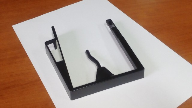
Pretty quickly, the 3D printed base plates also arrived (which will be ultimately crafted of aluminium):

3D printed base plates for the palm rest

And then the time has come to cover the foams with drape and put everything together:

Palm rest prototype

This is how the palm rest looks like when fixed to the UHK:

Palm rest prototype on UHK

We’re not ready yet. The type of the foam, the technology, and the drape to be used are not final. This continues to be an active area of development, and in our true style we’ll be keeping you in the loop.

LED display

Our LED display manufacturer has finished the mold of the display and created a couple of samples. This is the front side:

UHK LED display plastic part - front side

And the back side:

UHK LED display plastic part - back side

Next step, the PCB of the display will be put into the plastic shell, then it will be filled with epoxy, and a sticker featuring the graphics will be put onto the front side. We should get a ready-made sample pretty soon.

Finding our PCBA manufacturer

We’ve already picked about a dozen of suppliers who will provide all the different parts of the UHK, but a major manufacturer had yet to be found for assembling the PCBs.

So I started to request quotes from foreign companies, but when I received them, I stopped for a moment. “Wouldn’t it be great if we could find a nearby company?” - I thought. And then I emailed all 20 of the PCBA companies of Hungary and waited for quotes.

Then the impossible happened. It turned out that one of them is located in Kalocsa, the same small city where we’ll assemble the UHK. Not only are they next to us but they’re very responsive and interested in the project. We toured their facility and concluded that they’re the kind of guys we want to work with.

We’ve exchanged many emails and made a number of phone calls since then. These conversations are supremely useful, as we can heavily optimize the design of the PCB for manufacturing. As an added bonus, it seems like they can assemble not only surface mount components, but all the through-hole parts, so we won’t have to take care of those separately. We couldn’t wish for more.

And this is how we managed to insource PCBA by finding a company who is not 8,000 but 2 km away from us.

All hail our awesome contributors

Agent has been developed at a rapid pace lately, which leads me to introduce our latest and greatest contributor - Give it up for Mr. Mikko Lakomaa!

Mikko

I'm Mikko Lakomaa, a web developer from Finland. I've worked as a full stack developer for about a decade now but have shifted my emphasis towards front-end JavaScript development in the last few years. I got interested in the UHK when I was looking for a more ergonomic keyboard and it just happens that their software uses technologies I wanted to learn so I decided to help them out.

Over the last few weeks, Mikko has managed to push the Macro UI of Agent to the next level, so mad props go to him along with a UHK with all the bells and whistles. Thank you so much for your contribution, Mikko!

Jozsef and Nejc are also pushing hard and have been making solid progress. Nejc has implemented the add keymap UI of Agent and now working on the data layer which manages the internal state of Agent. Jozsef has been implementing his fair share of refactorings and reviewing a fair number of pull request as the lead developer of Agent.

And now to the second part...

Choosing a switch brand

We have just decided which switch brand will be used for the UHK. Our campaign page mentions Gateron or Greetech as possible candidates, but in order to make the best choice we ended up considering other brands, too.

It’s important for us to share our thought process with you, so we’ll go over all the brands one by one and highlight some major points.

Cherry

Cherry MX switches

Cherry is hardly stranger to anyone, given that they’re the original designer and manufacturer of Cherry MX switches. Then their patents eventually expired, and other brands entered to the market and replicated their switches.

Cherry is the most trusted brand because they started the show, and they’re still in business after all these years, so it’d make logical sense to pick them over the others except for one thing: availability.

The supply chain issues of Cherry MX switches have been prevalent over the years. Cherry is known for striking exclusive deals with the top keyboard manufacturers of the world, much to the dismay of smaller manufacturers who weren’t able to source Cherry switches in a consistent-enough manner to manufacture their products.

Some manufacturers switched from Cherries to alternative brands, and were accused of cheaping out. We doubt that these guys were actually cheaping out. Some of them might have, but others simply wanted to get their products manufactured. We don’t want to be ever put into this situation.

Availability issues have been well known for long time, so back in the day I ended up phoning Cherry’s German sales office only to be informed that there’s nothing they can do about supply chain issues.

Given the above, we’ll only use clear and green Cherry switches because no other manufacturers create switches of such types, but for everything else we’ll use another brand.

Gateron

Gateron switches

Gateron switches are well known and loved by the keyboard enthusiast community. Gateron manufactures quality switches and trusted by many, so it’d make sense to pick them. We have two issues, though.

The first issue is the lack of direct contact with Gateron. Call us old school, but we like to get involved with manufacturers to be able to discuss any potential issues. We weren’t, however, able to reach Gateron neither across the Internet, nor via phone. We even asked a friend of ours in Hong Kong to try to get in touch with them, but he wasn’t able to.

We would much rather do business directly with a manufacturer than using a buying agent. Again, it’s not because of the slight added cost, but the ability to directly communicate with them.

The second issue is that Gaterons use milky white plastic for their housing. This shouldn’t be a problem for most keyboards because the switches underneath the keycaps are hardly visible, but it’s a different story for the UHK. When the halves are split the milky white color becomes visible, and it doesn’t gel well with the rest of the keyboard which is usually black.

Because of this, we don’t consider Gateron an ideal choice for us, and would rather pick an alternative brand.

Greetech

Greetech switches

Greetech switches resemble the look of Cherry switches the most closely. It’s very easy to miss the difference because the shape of the two seems identical. Only the text featured on the housing of the switch tells whether it’s a Cherry or a Greetech.

The Greetech switches we tested felt great. Being very similar to Cherries makes them a great choice for us, not only functionally but visually. They offer 4 MX switch types (each with or without stabilizer pins) and 2 low profile switch types.

Greetech is a great candidate, but our story doesn’t end here. We wanted to go all the way and consider every switch type.

Outemu

Photo is courtesy of Massdrop

Photo is courtesy of Massdrop

Truth to be told, we don’t know a whole lot about these switches. We can see them being used in various, mostly Chinese keyboards, but we couldn’t even find their website, and have no way of reaching them directly, so our main concern is the same as for Gateron switches.

Kailh

Initially, Kailh wasn’t on our radar because we assumed that they only strike deals with large companies and don’t serve small startups like us.

Eventually, our keycap and keyswitch supplier recommended Kail switches. He’s a guy who is also a keyboard designer, deeply passionate about keyboards, and very concerned about quality. In his opinion, Kailh switches are better than other MX compatible switch brands.

Today, I tested about 500 Kailh switches by hand and although I’m not a perfect switch testing machine, every one of them felt great and consistent. András has made a couple of blind tests and he put Cherry and Kailh into the same group 3 times in a row and put Gateron and Greetech into another group. This doesn’t necessarily mean anything, but it might mean that the feeling of Kailh switches resemble Cherry more than other brands.

There are a couple of points to be noted about Kailh. They’re a major MX switch manufacturer with more than 2,000 employees. Their manufacturing process is highly automated which should translate to great and consistent quality across their products. Their supply chain is robust and they have plenty of stock, so they can serve their customers without significant delays. Their sales channel is responsive. Kailh also manufactures automotive parts which is encouraging, because automotive manufacturers have to comply very strict quality guidelines.

Kailh’s MX switch offering is unusually rich. They offer switches of different case colors (black and transparent), optimized for regular LEDs, RGB LEDS, and SMD LEDs, and are available with or without pins.

From the innovator’s point of view, an even more interesting fact is that Kailh is not just a copycat. They recycle a significant portion of their capital into R&D, resulting in new products like the following:

Special Kailh keyswitches

Most of these keyswitches are not MX compatible but they offer various advantages over standard MX switches, like lower form factor, improved backlighting, and such, allowing developers to create new keyboards that stand out in various areas. We consider this a good thing.

Making the decision

When googling for keyswitch comparisons, one can find tons of opinions and very few facts. Some people or communities pick a brand to glorify or berate for little or no reason. We always try to be as objective as possible, and make the best choice that will result in an exceptional keyboard.

Considering all the factors, we have decided to use Kailh switches for blue, brown, red, and black, and Cherries for clear and green.

It’s important to mention that our decisions are not primarily governed by the price. There’s little difference between the price of Cherry MX compatible switches, and if we really wanted to cheap out, the first thing we’d do is to replace the super high quality Omron SS-01D microswitches of the case buttons with a cheaper part. One SS-01D switch costs about as much as 10 MX switches but the alternatives of the SS-01D have inferior durability, so we’re not willing to use those.

2018-04-28: As it turns out, Omron microswitches are reasonably priced when purchased in bulk, but they're hard to purchase in large quantities. Our PCBA contractor suggested an alternative part, the Diptronics MS2-5PN-1D(Ag) microswitch. After examining this part, we found that it represents the same high quality as the Omron SS-01D. I wanted to clarify this before being accused of cheaping out. As a general rule of thumb, we never use alternative components unless we're sure that they're of the same high quality as the parts in our BOM.

As you can see, there are a lot of factors, such as quality, availability, and aesthetics that come into play when picking a part. We think that, given the above, Kailh is an excellent choice and we’re excited to use their keyswitches in the UHK.

Should you have any opinions, you’re always welcome to let us know.

It’s been a pleasure to talk to y’all! Let’s touch base on 2016-10-13.