Improved EMC test results and incoming parts
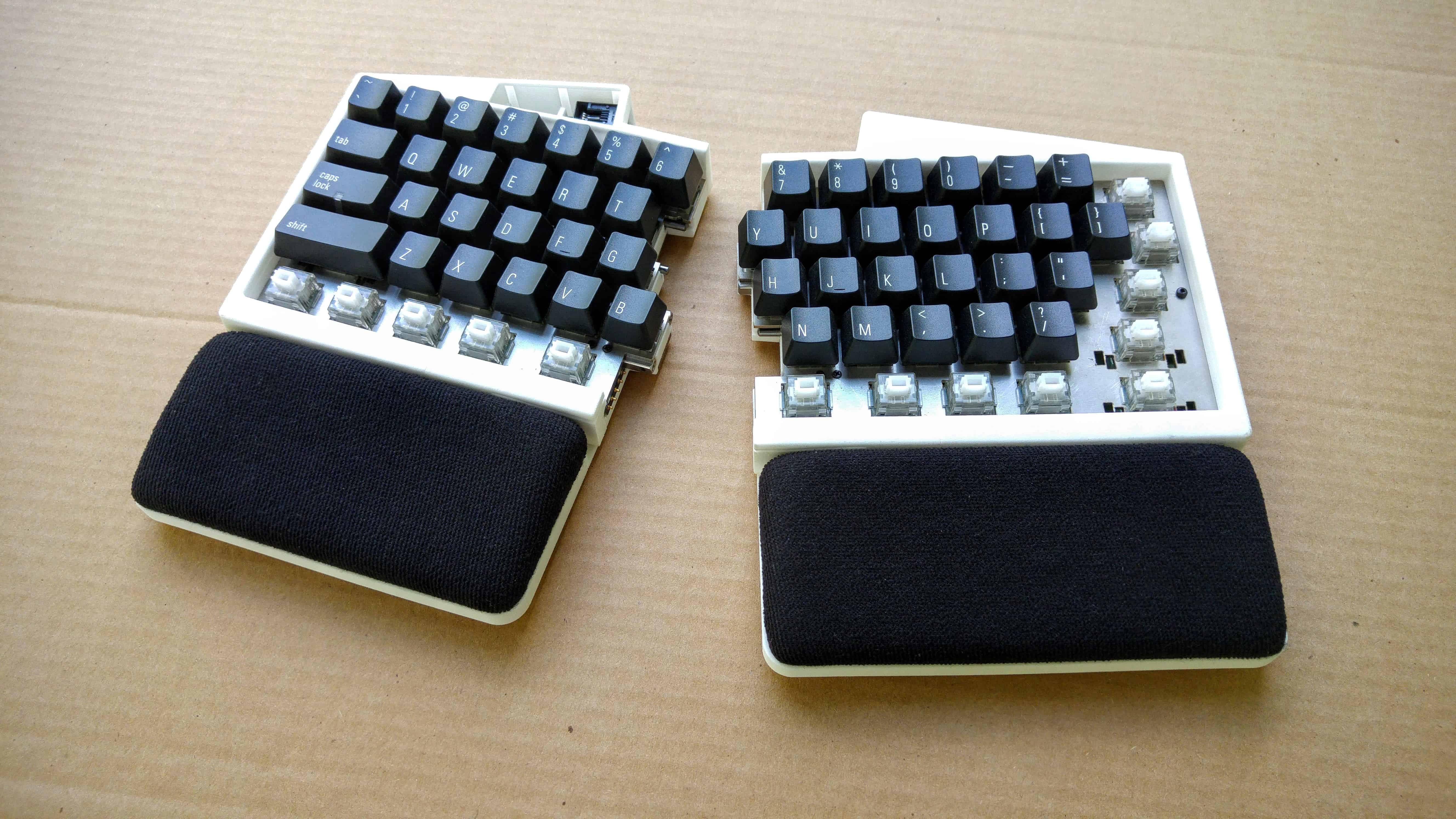
Hello, and welcome to this month’s UHK update!
TL;DR: Our most recent EMC test results are much better than the previous results, but they’re still not good enough. We’re working hard on our new prototype to pass the tests, but this delays the project by about a month. Lots of progress is happening on other fronts, too. Please read on!
Parts are flowing in
The UHK contains loads of components, and some critical ones are flowing in one by one. These are the most recent parts:

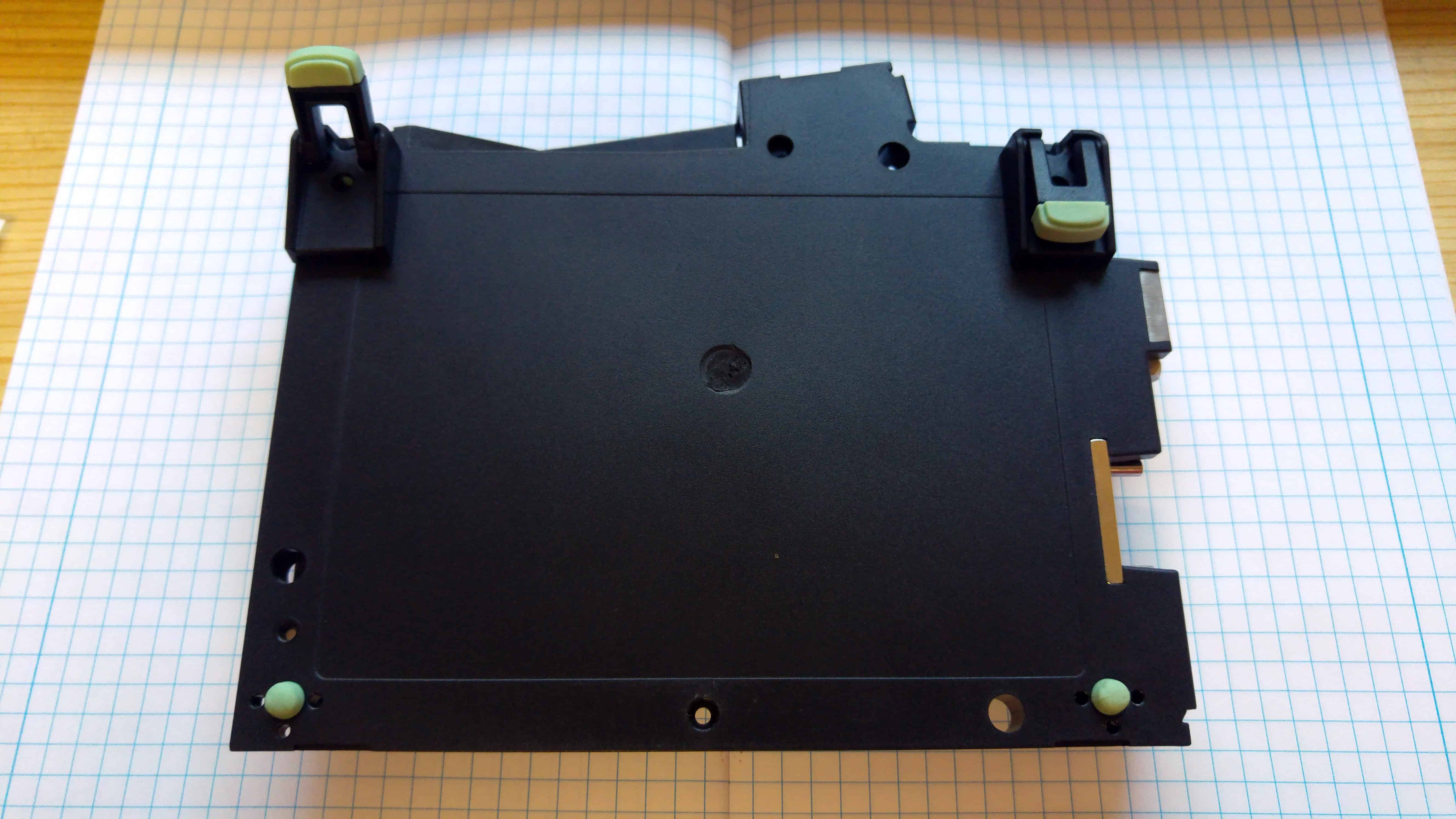
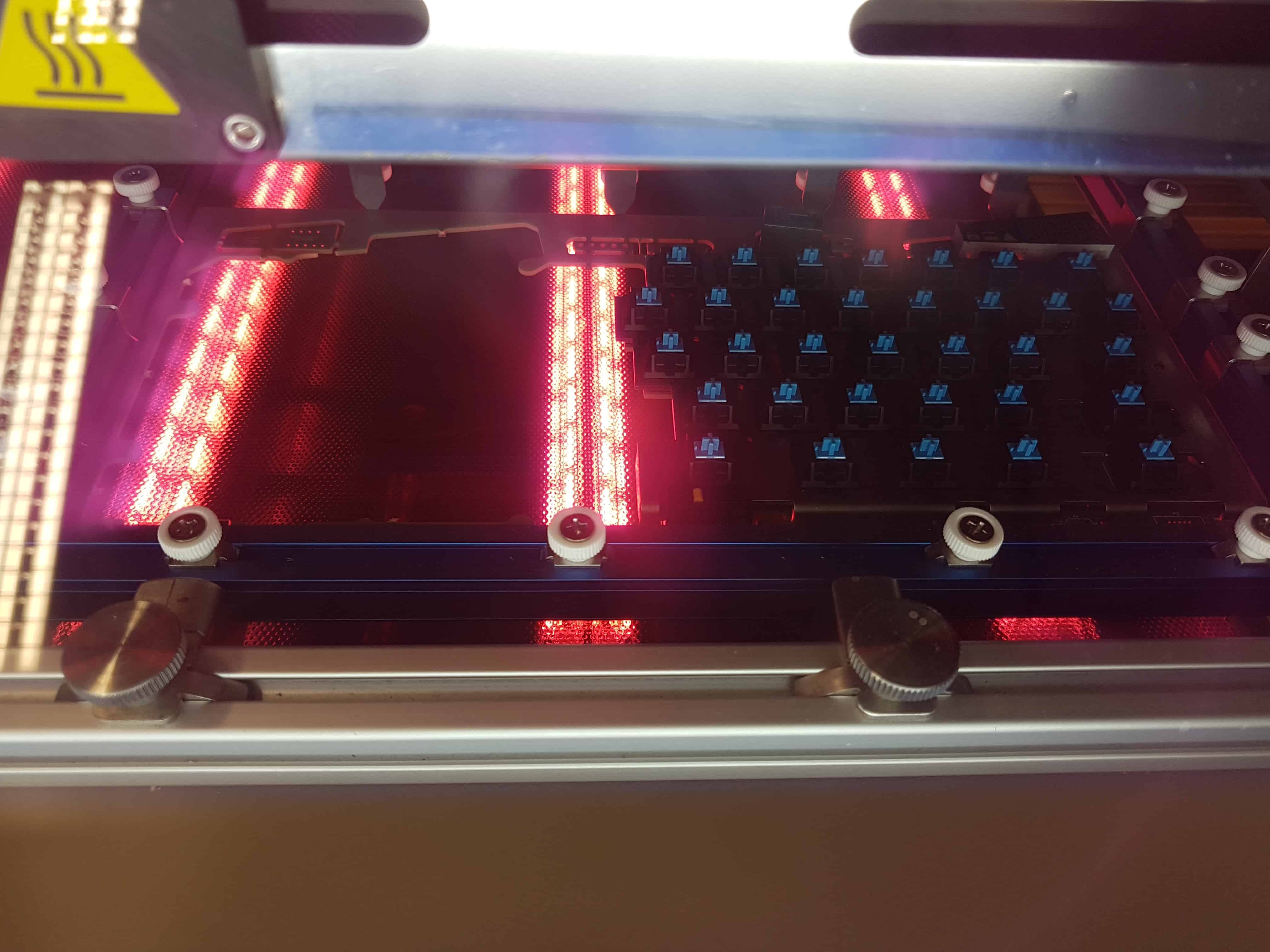
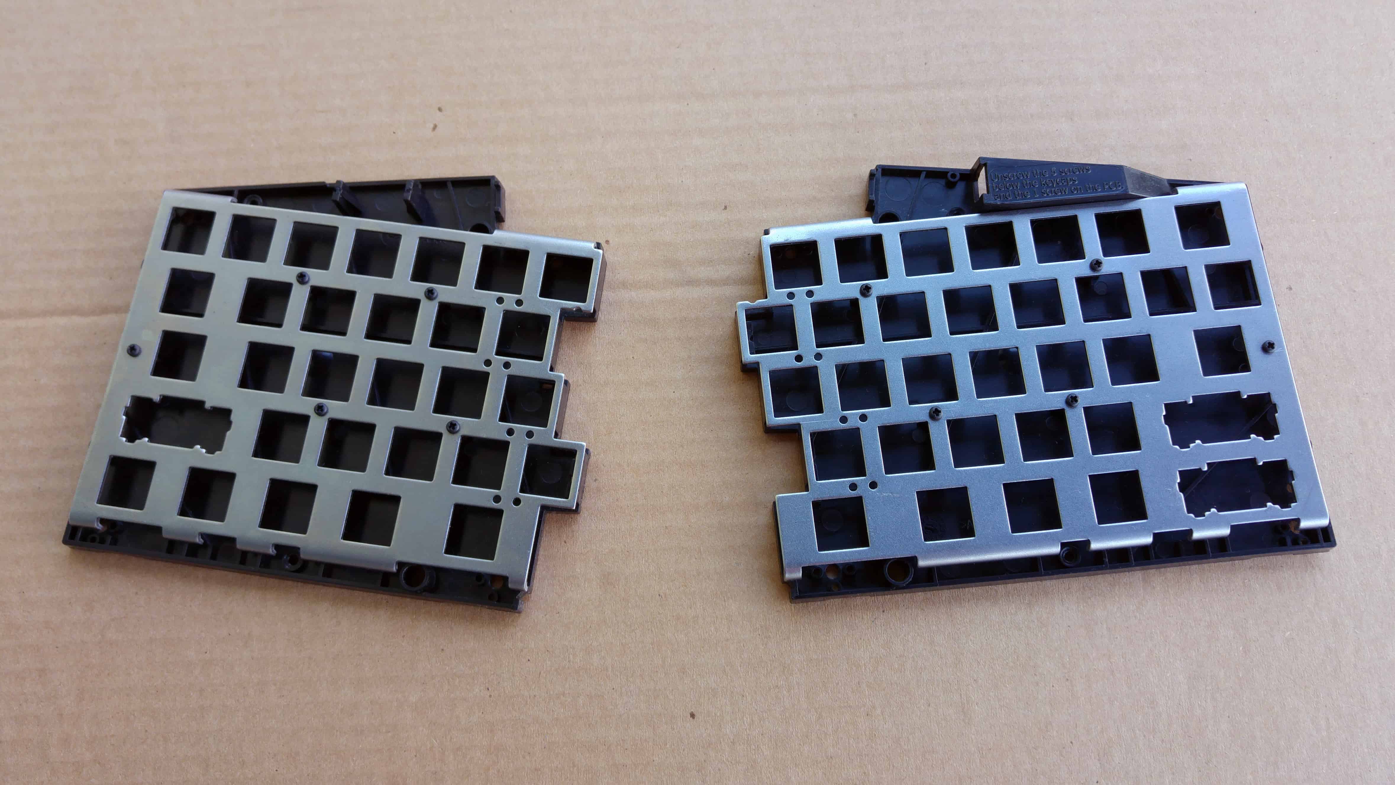
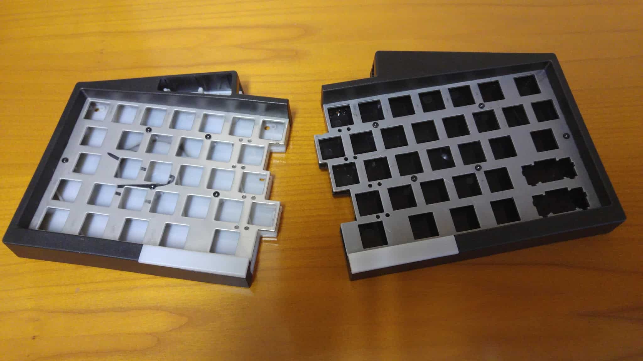
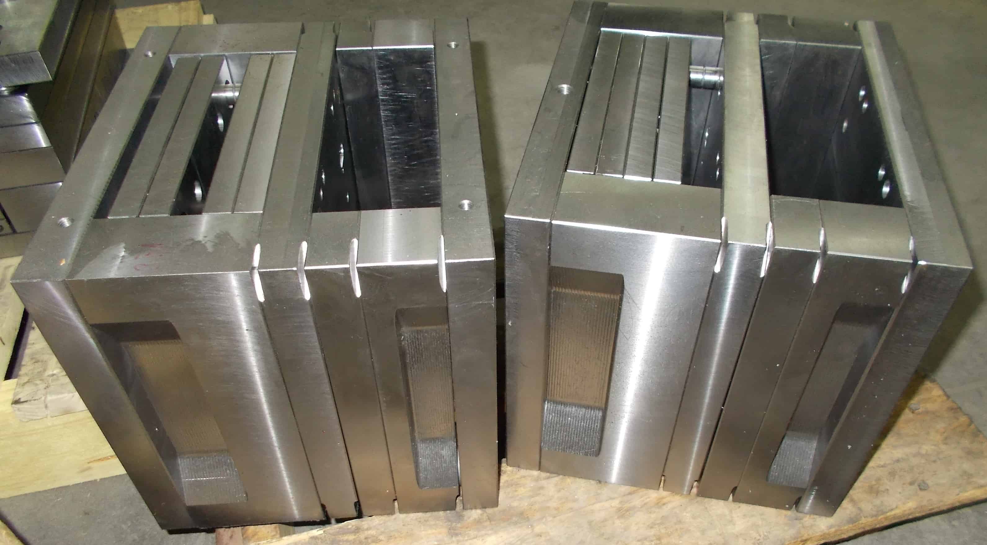
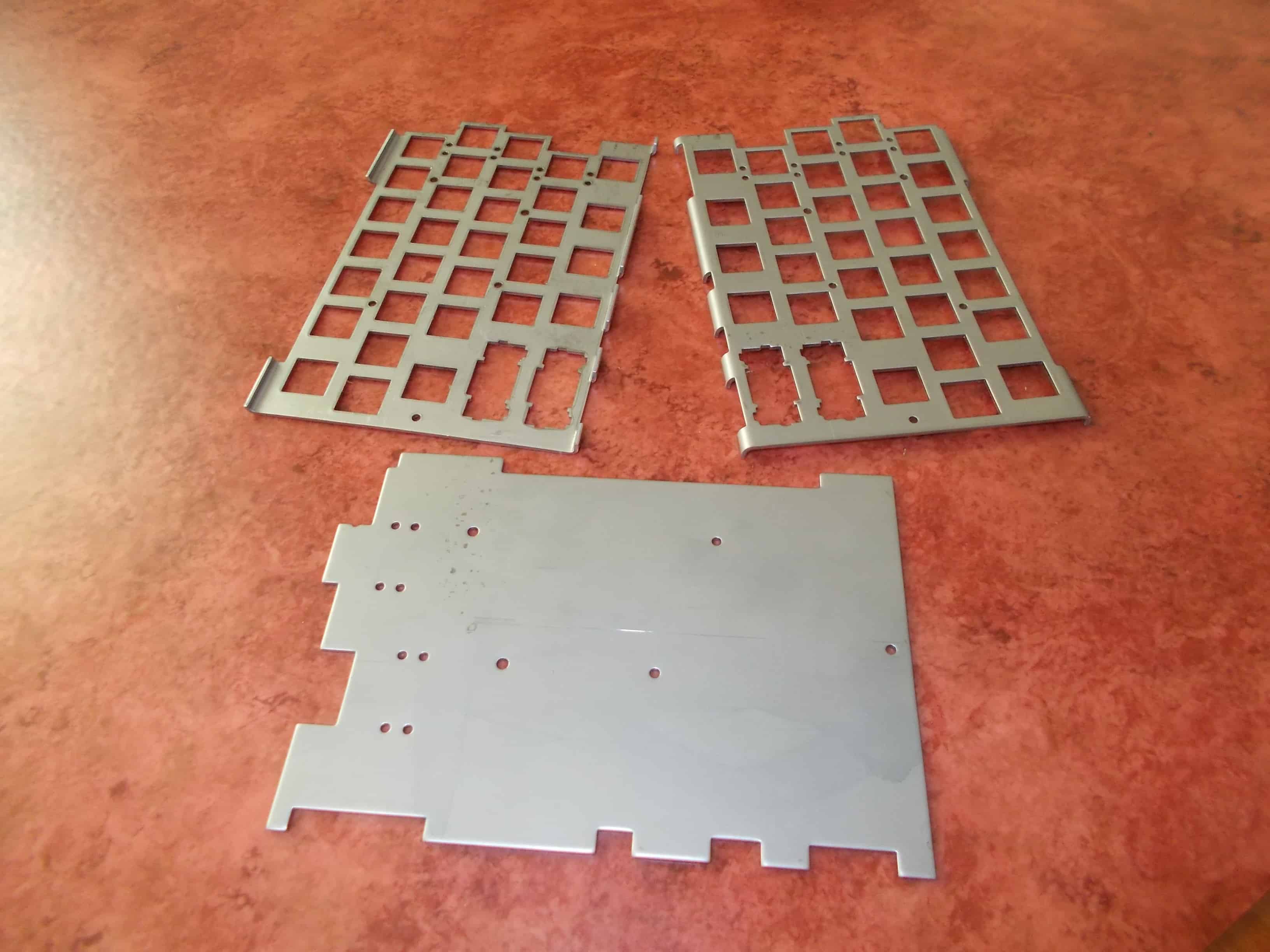
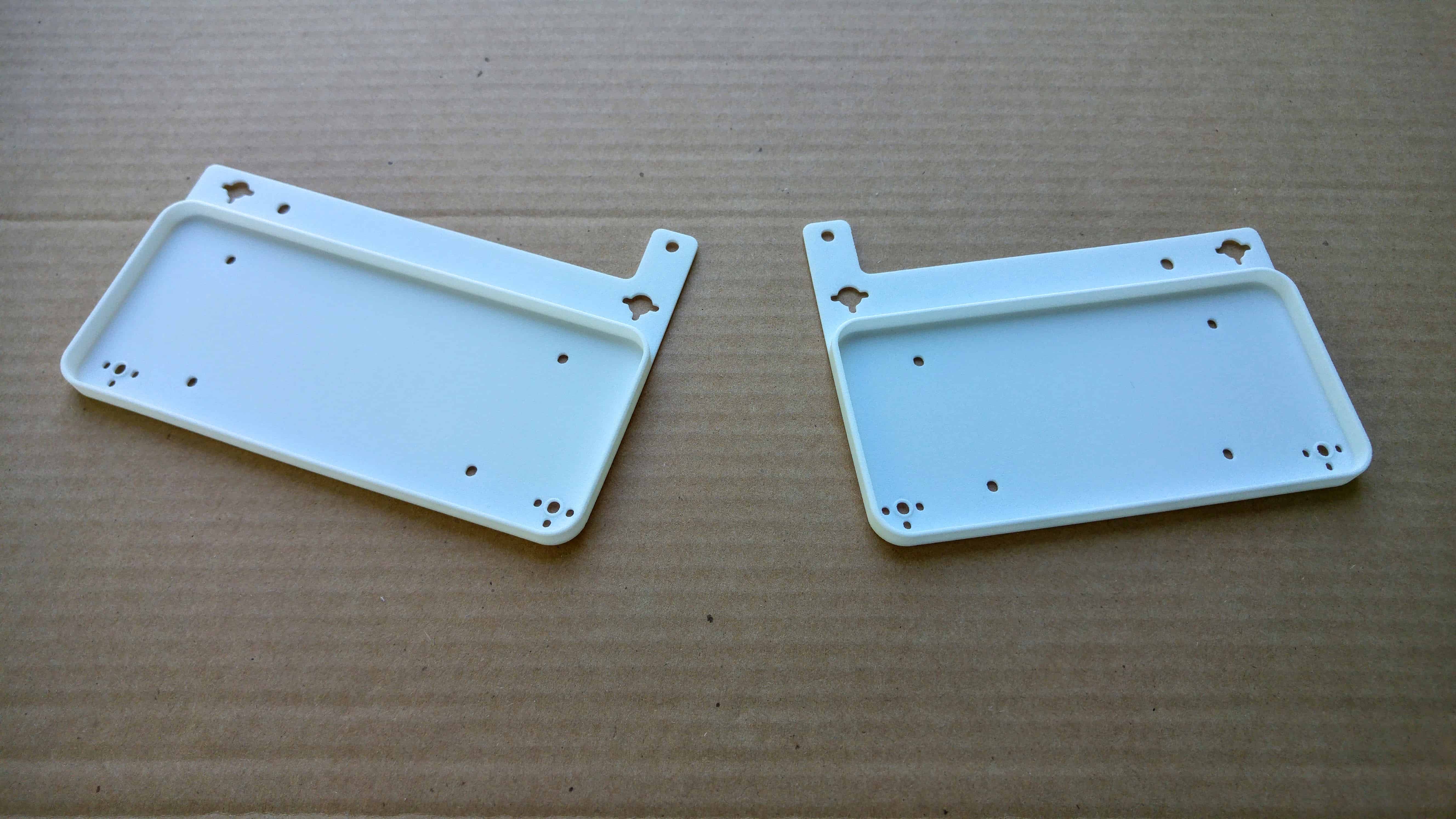
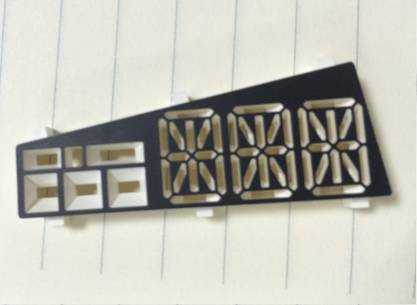
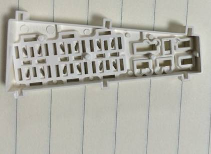
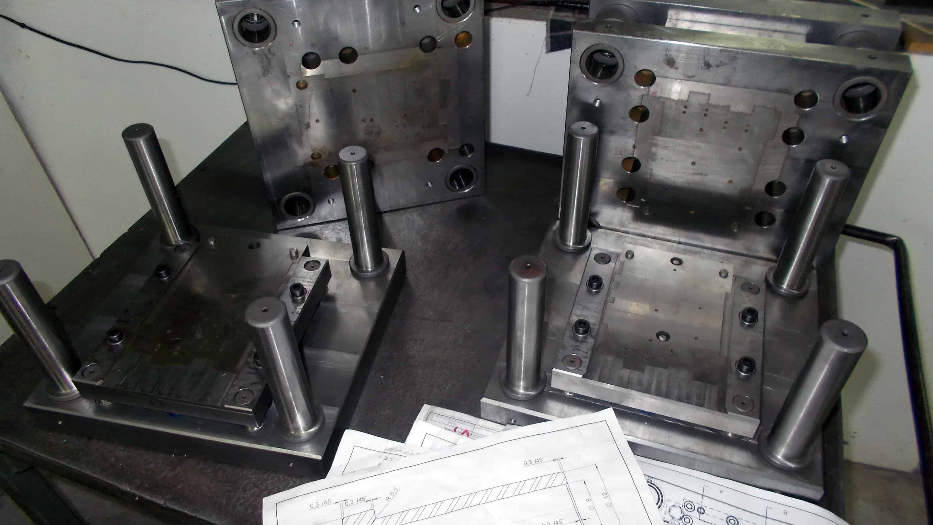
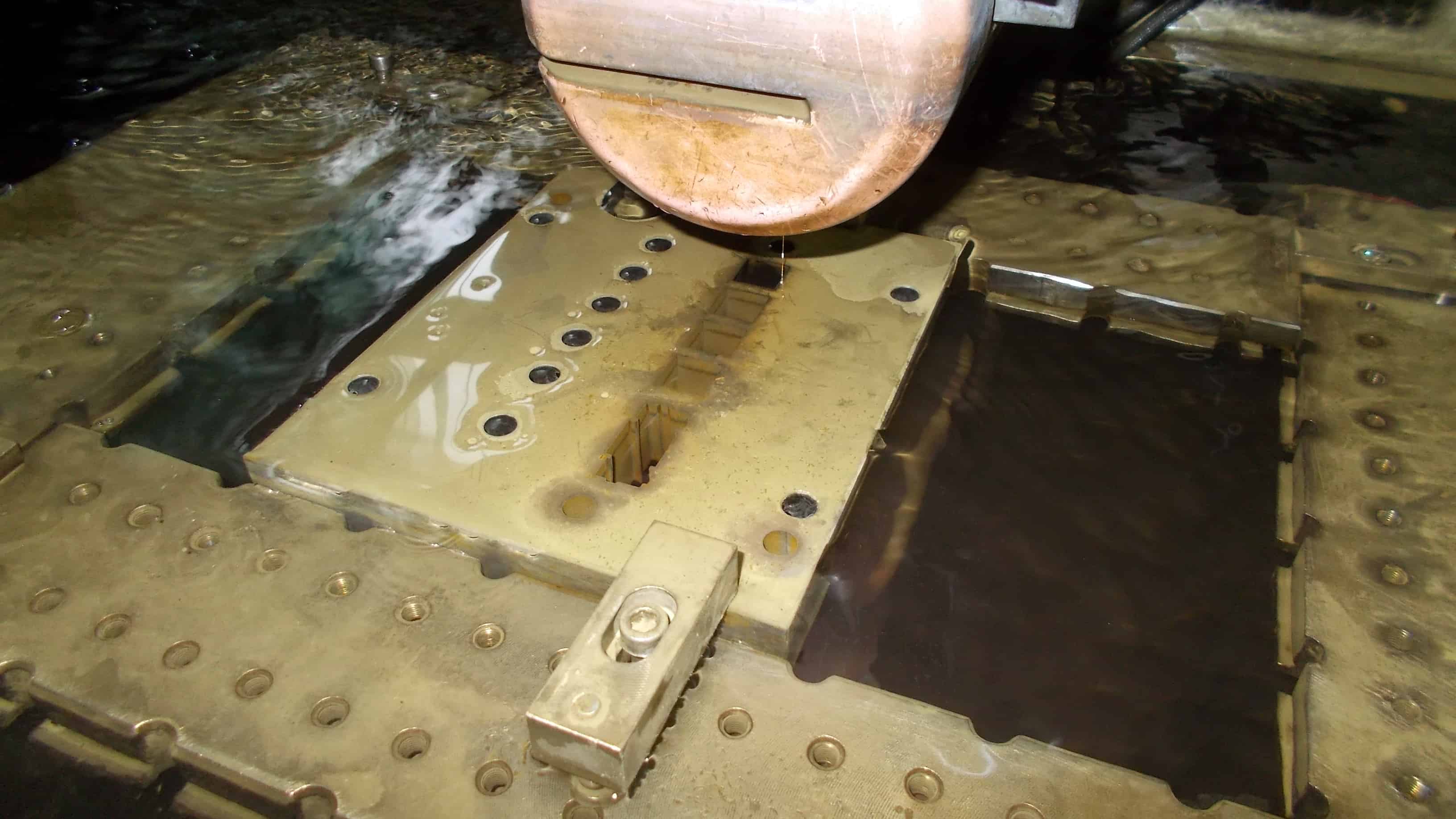
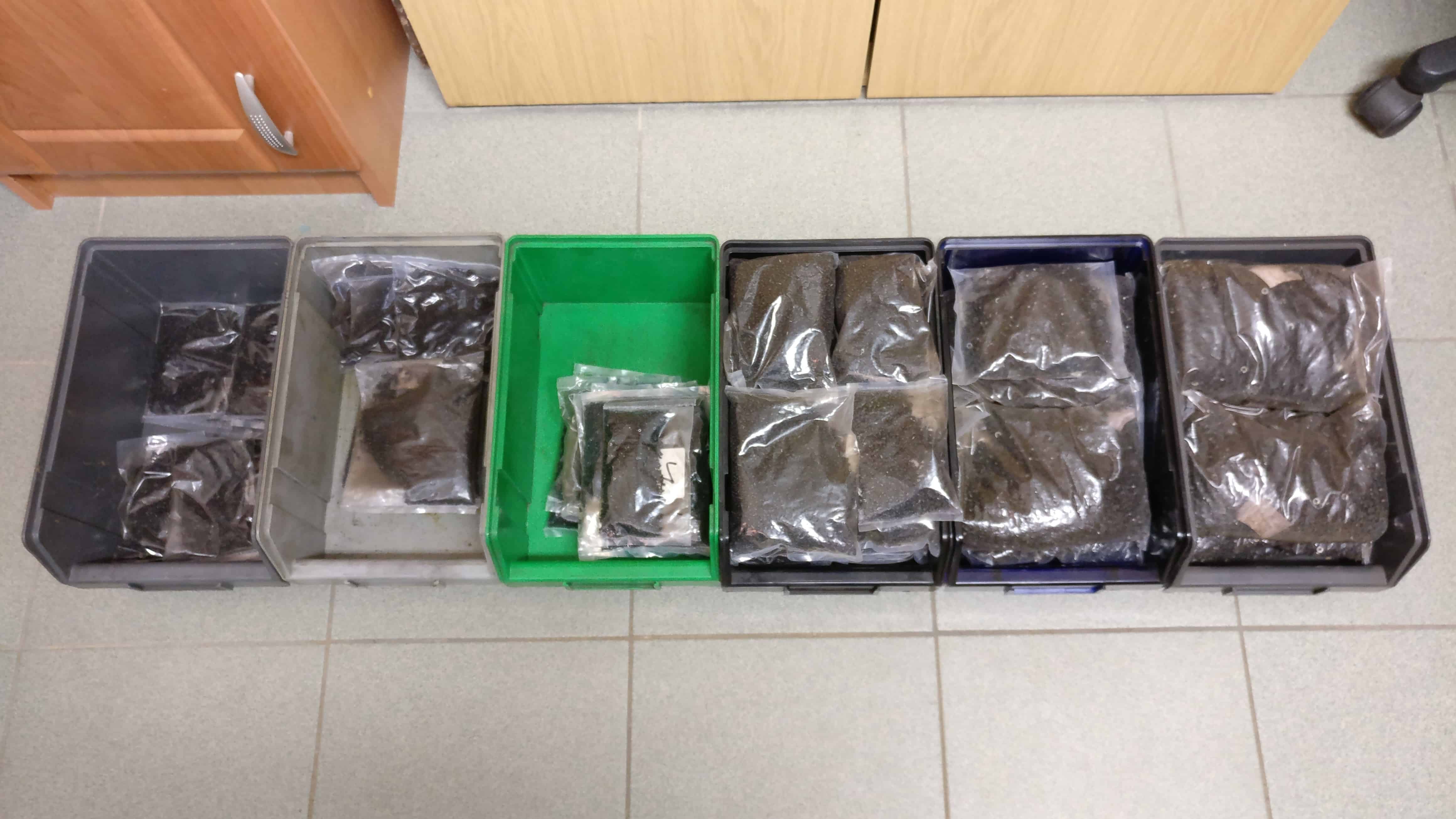
100 ANSI left, 100 ISO left, and 100 right plates have been manufactured so far. These plates will be used for the first production run. Of those plates, we have 20 of each in hand to check their quality and accuracy.
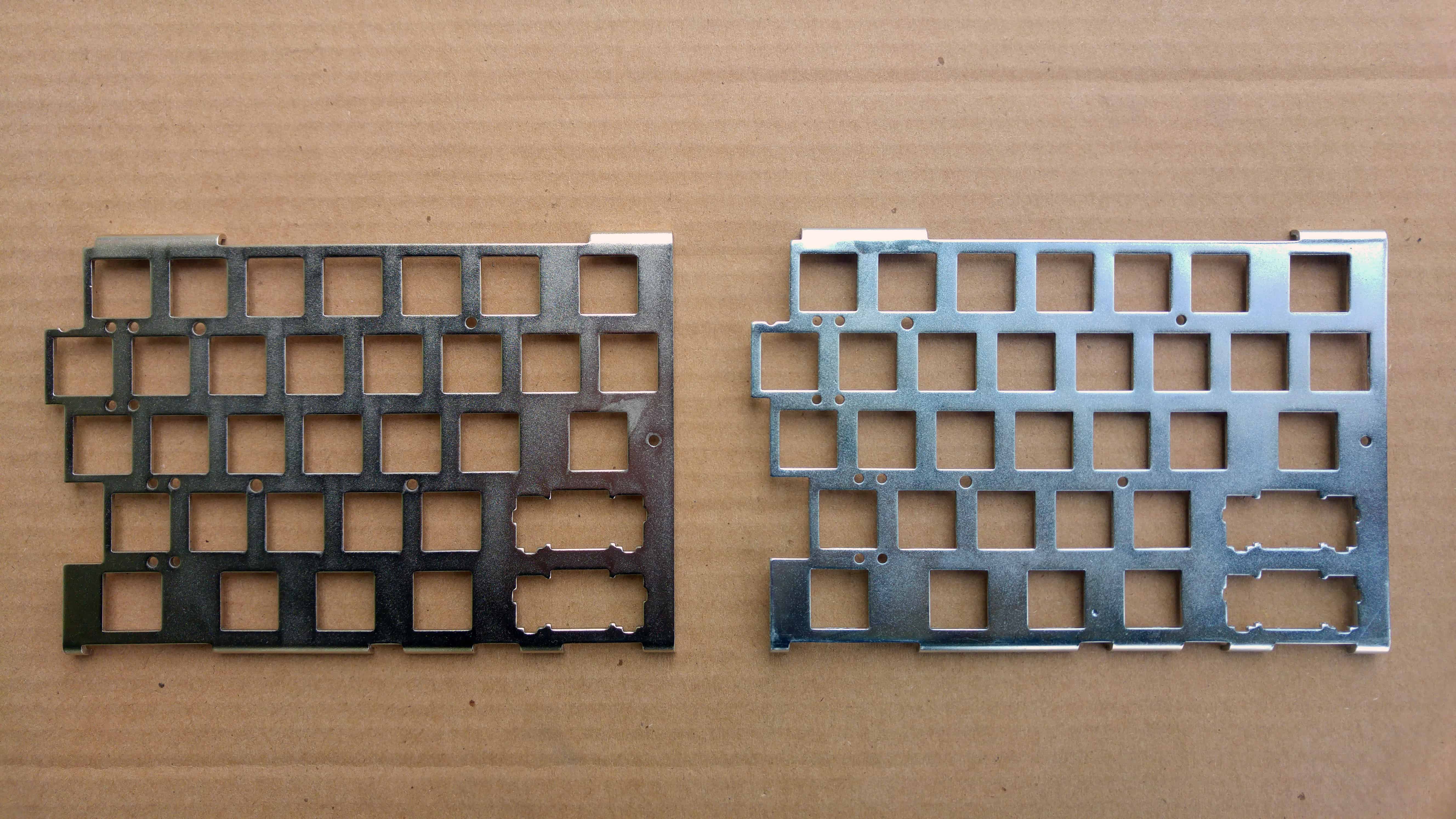
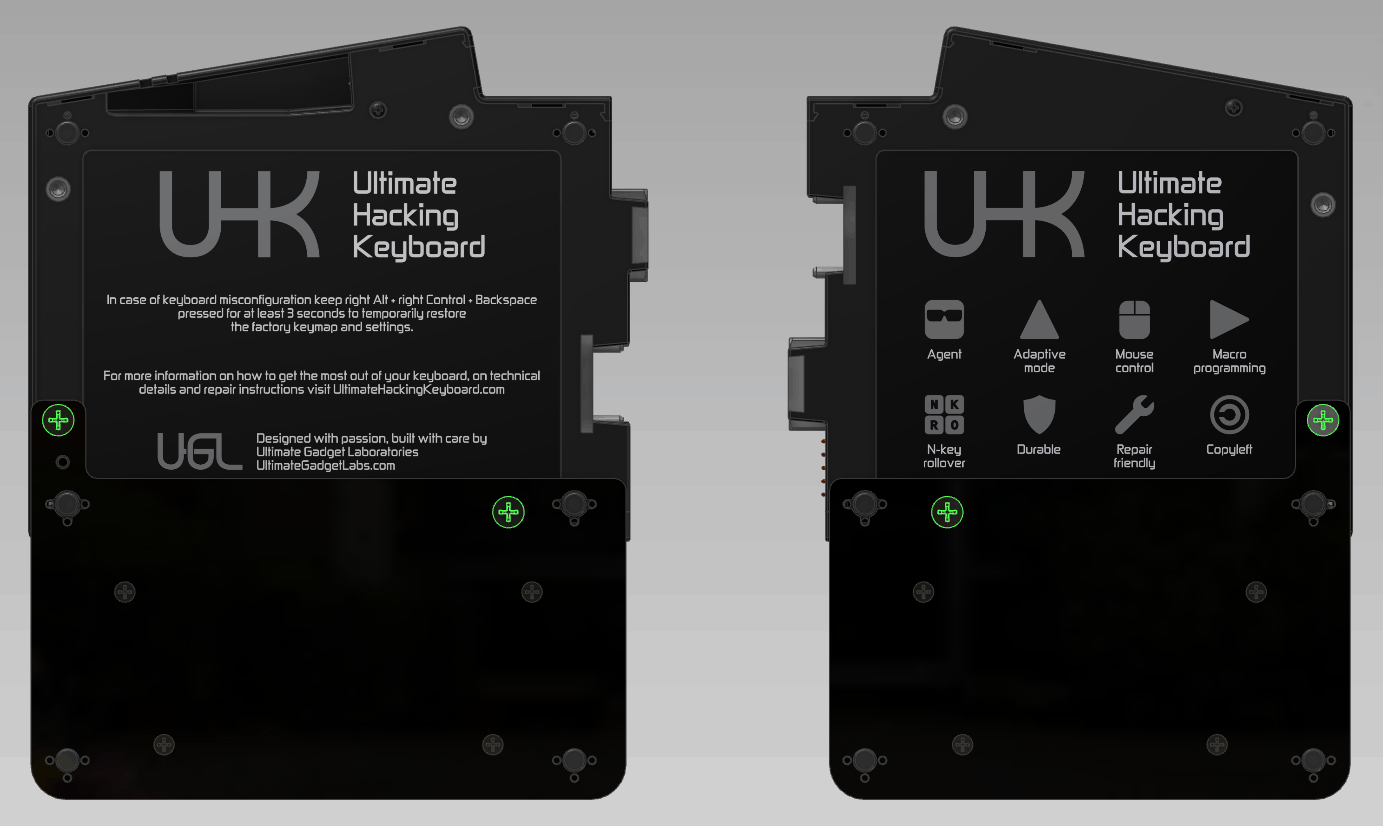
These 2 plates were surface treated with Nickel and Zinc.
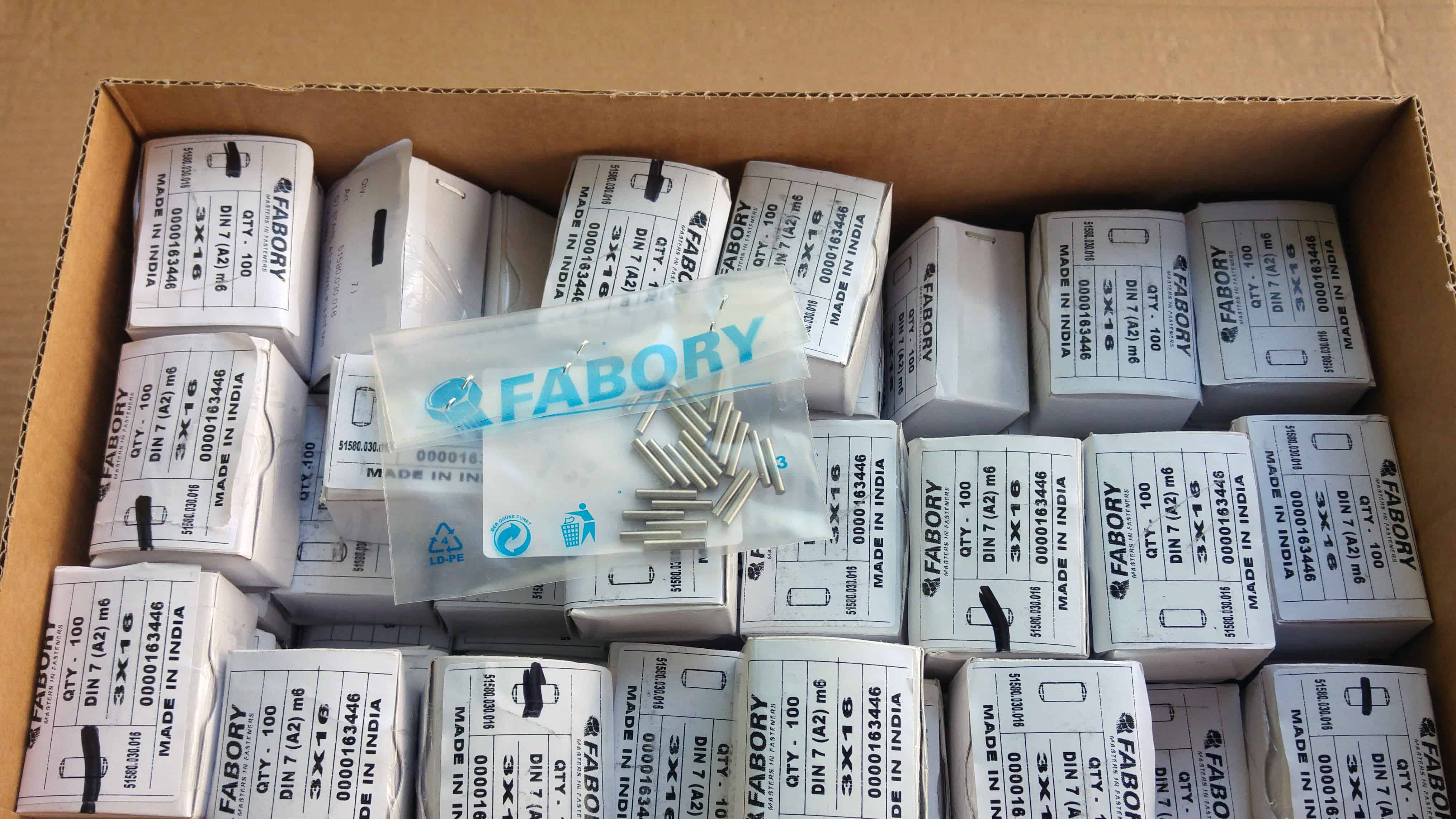
There are also loads of smaller components that arrived lately:
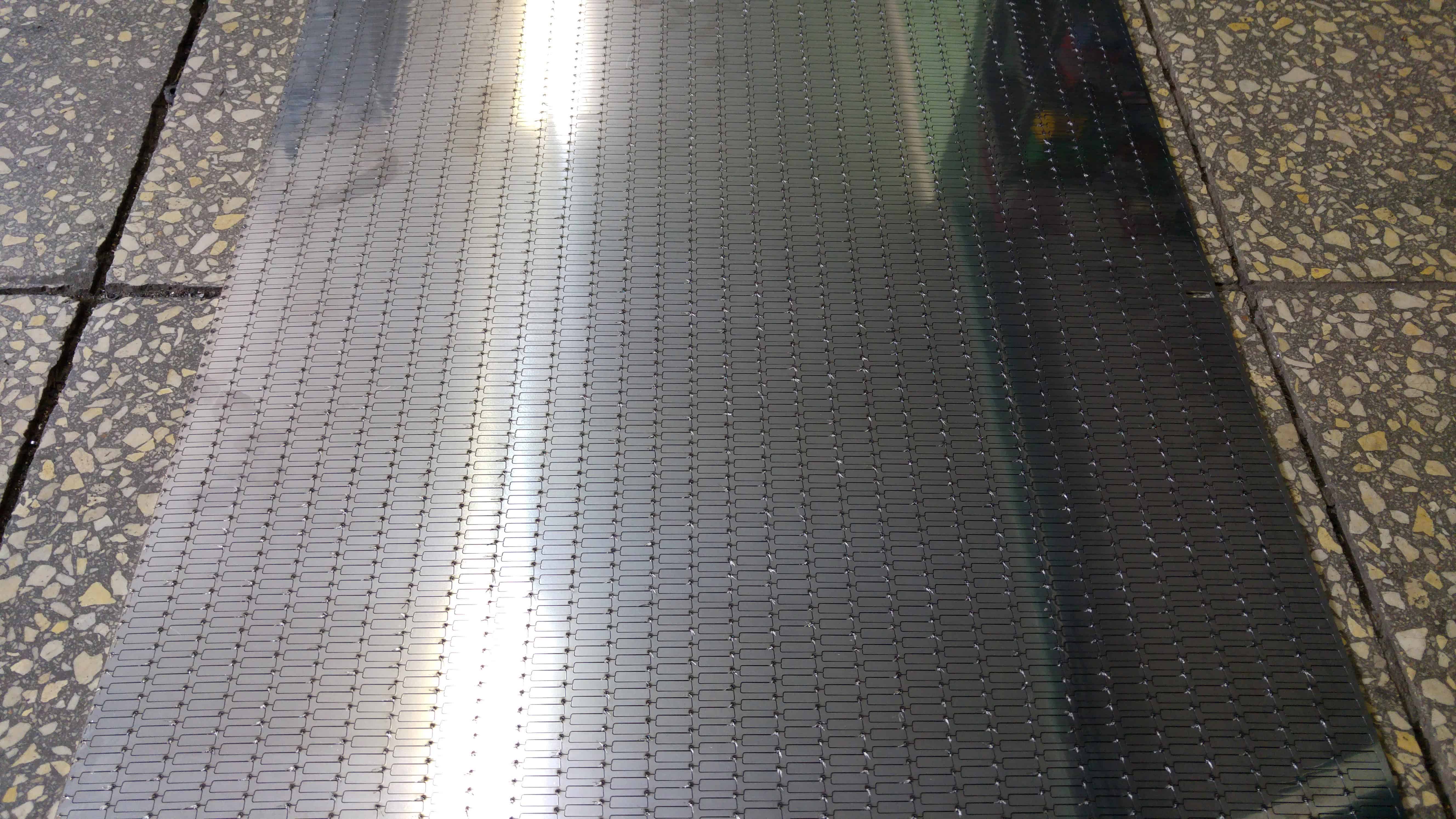
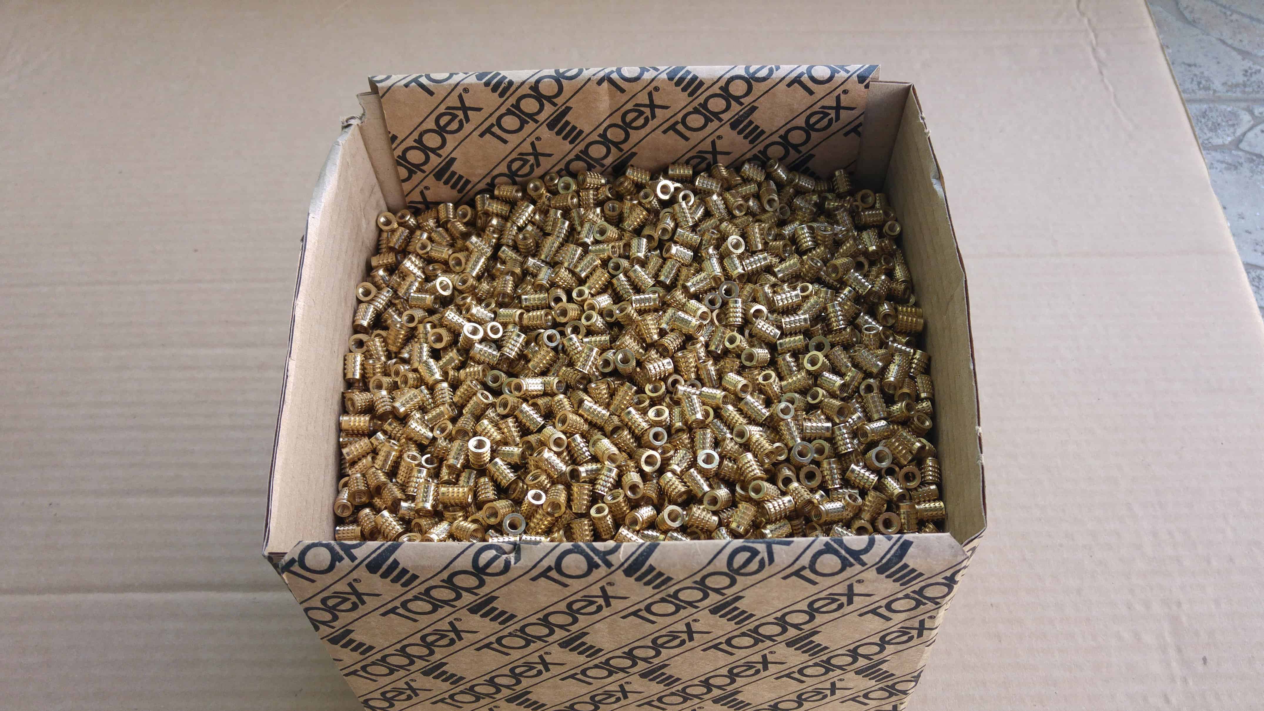
4,000 magnet counterparts laser-cut
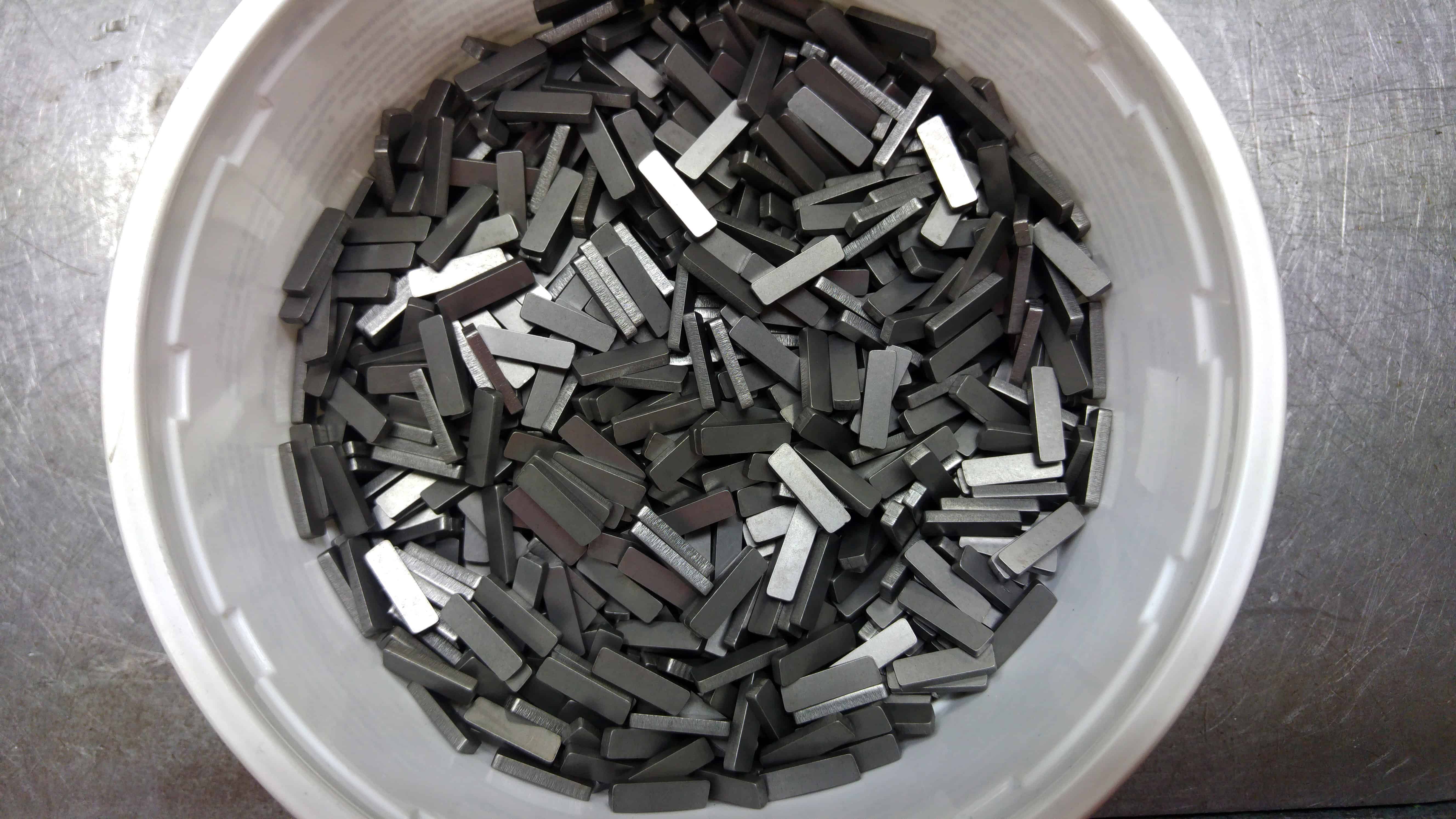
A couple magnet counterparts after grinding
140,000 screws
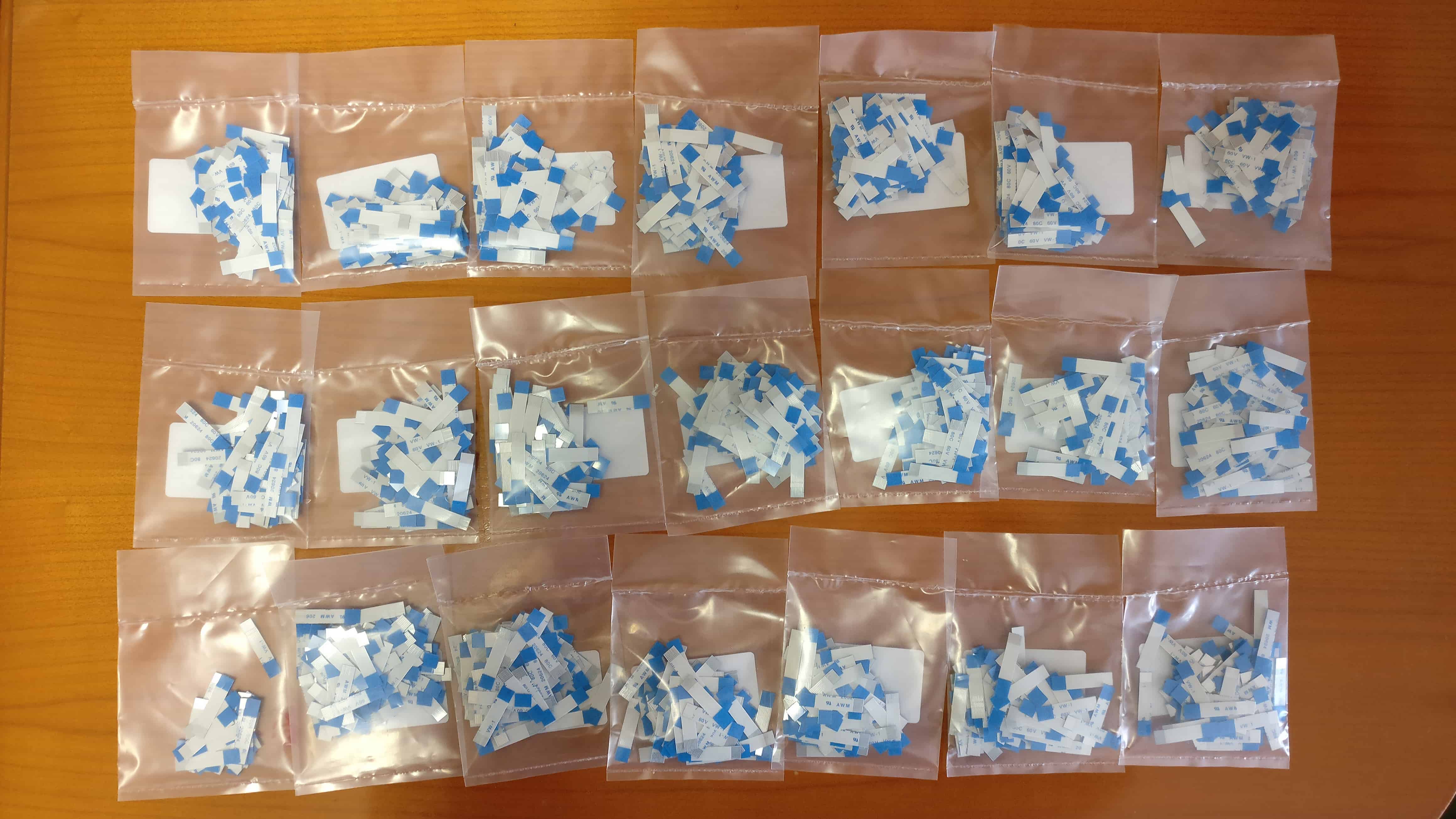
2,100 FFC cables
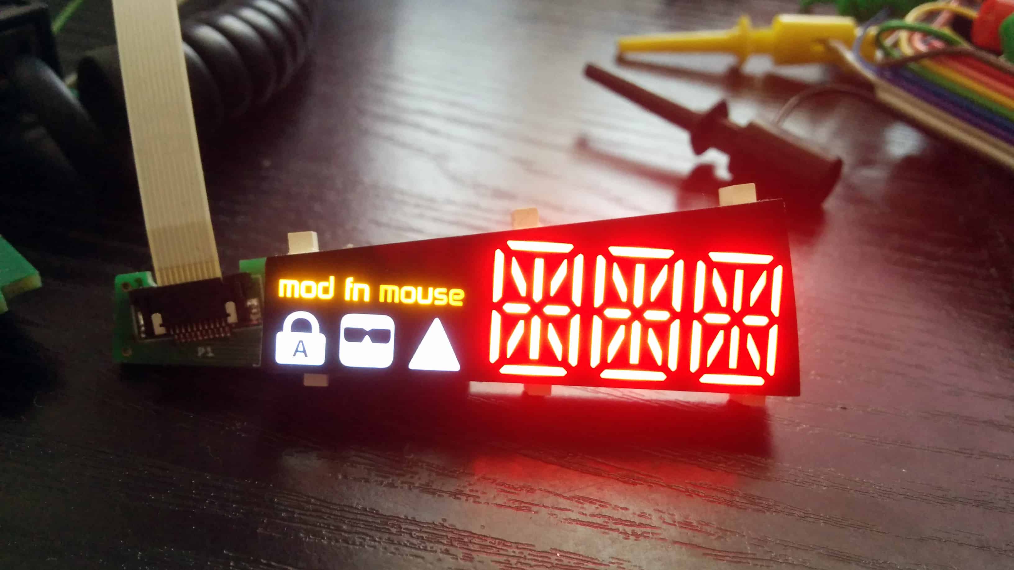
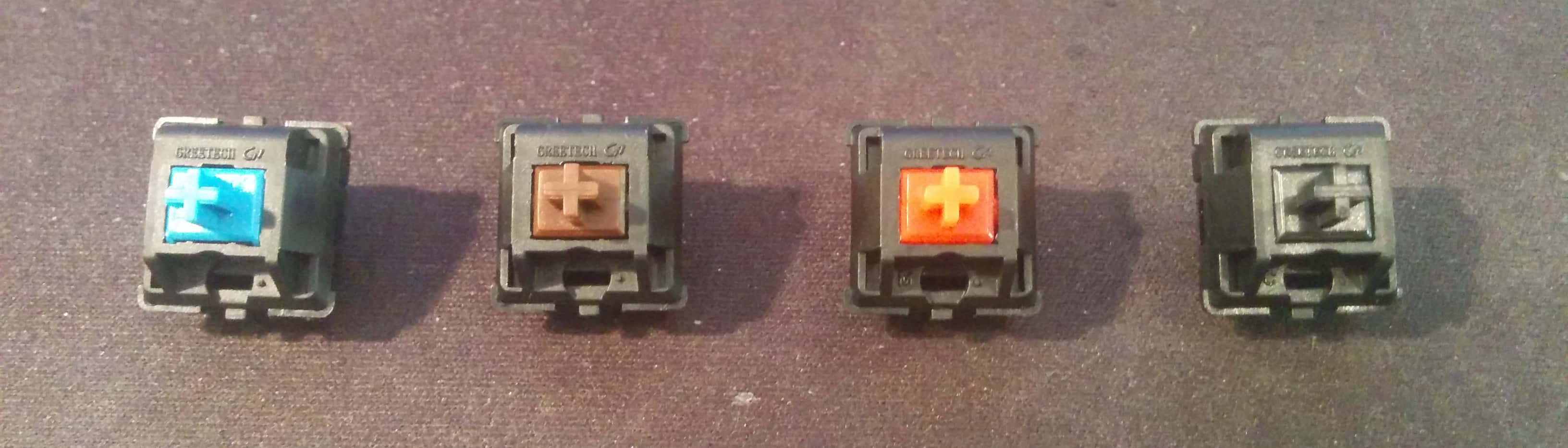
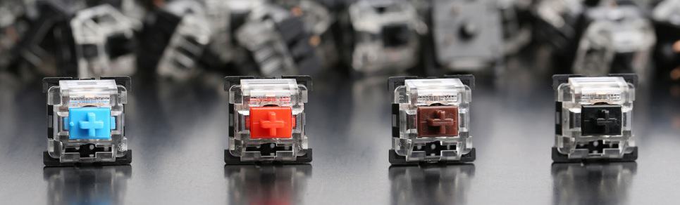
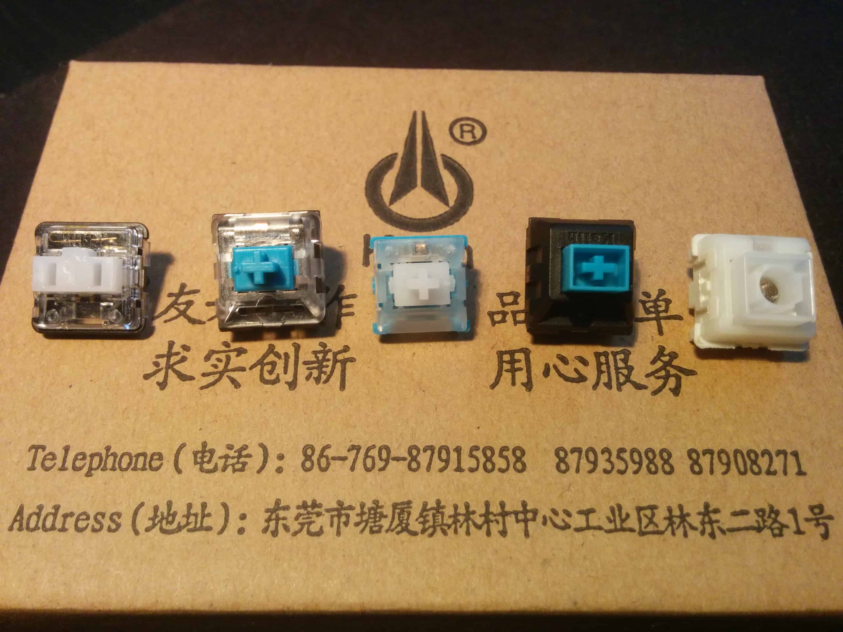
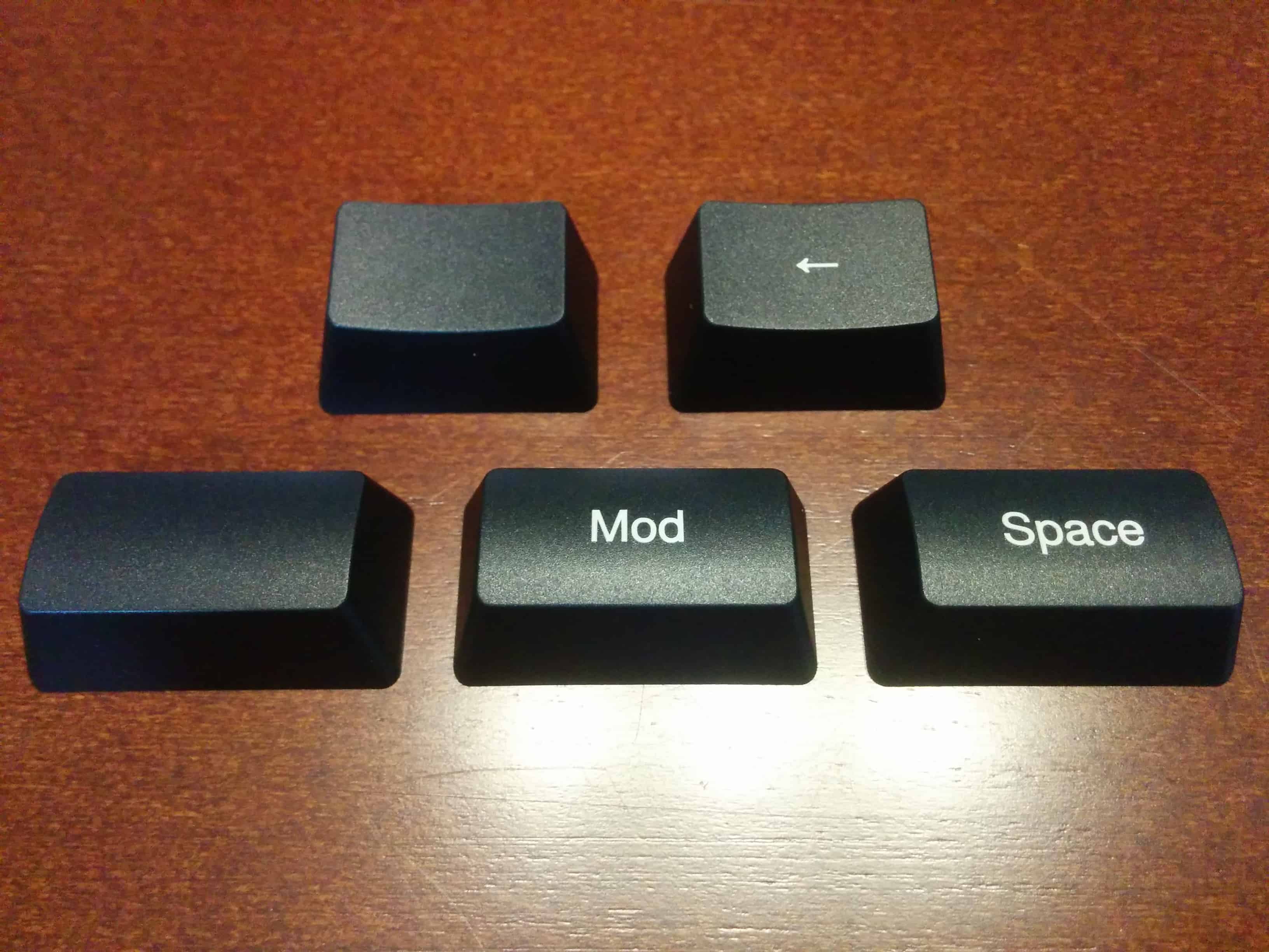
We’ve already ordered the switches, keycaps, keycap stabilizers, and displays which are expected to arrive soon.
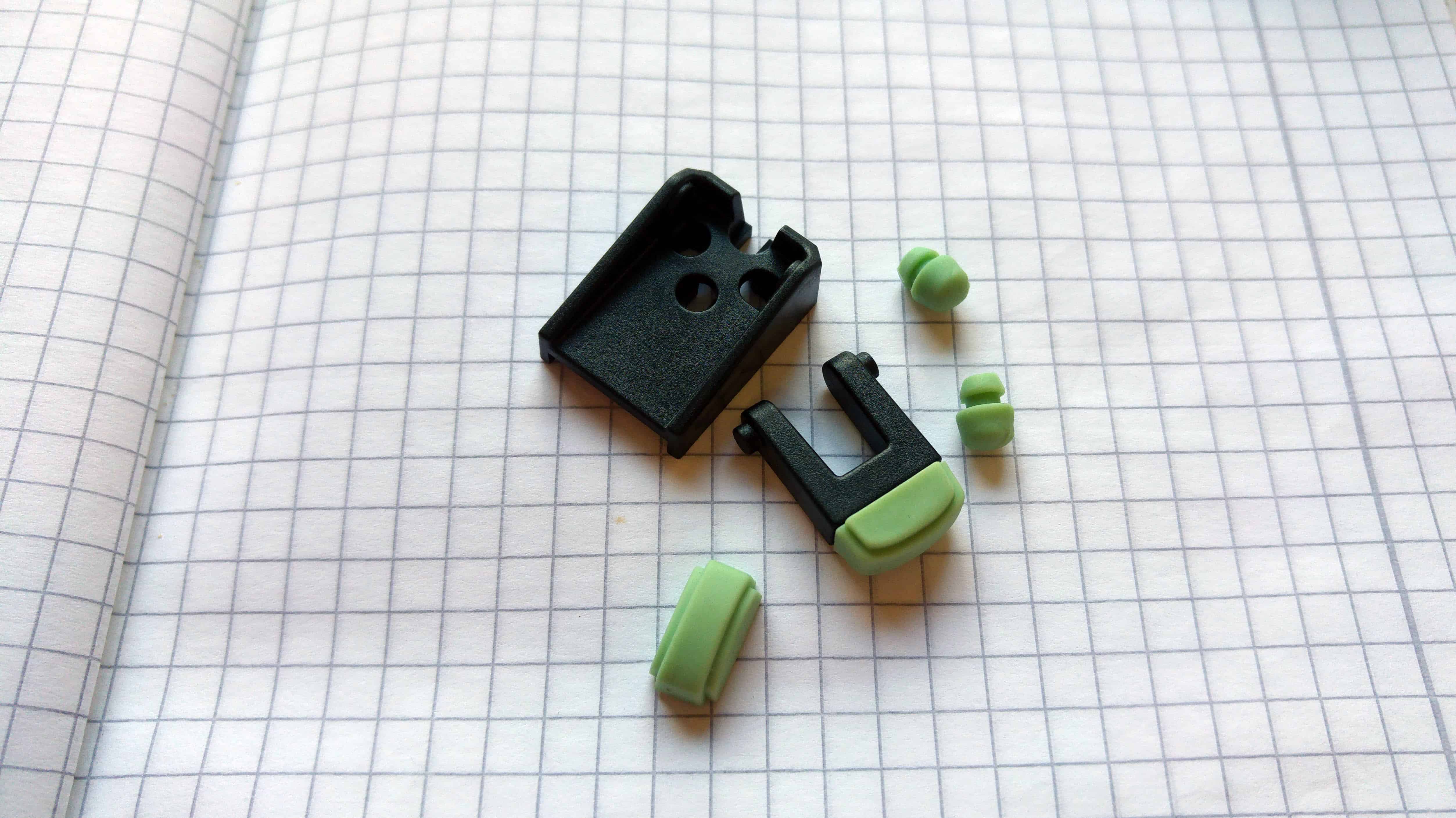
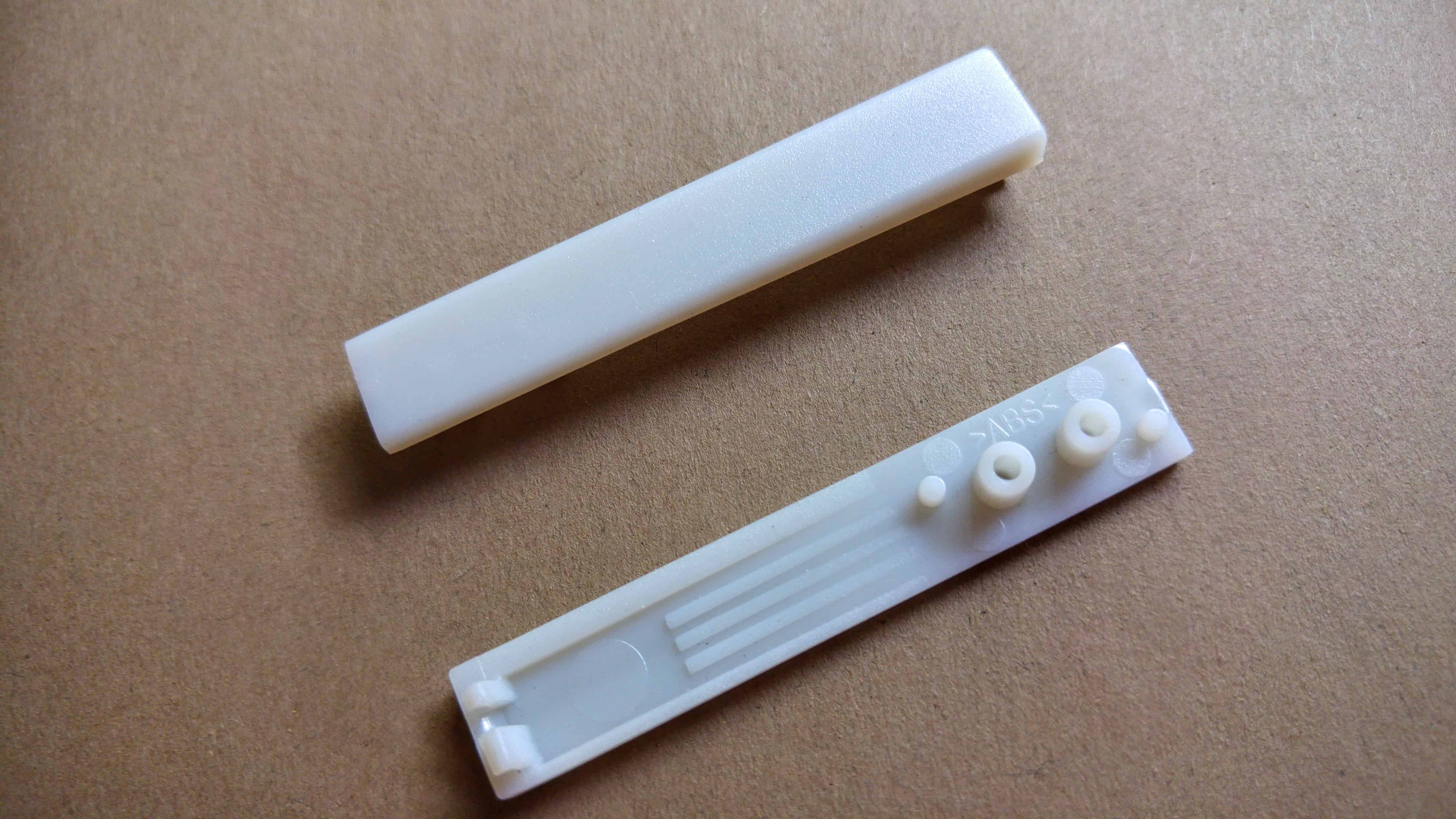
The manufacturing of the guides and magnet counterparts is in progress. These are multi-step manufacturing processes, and they’re well underway.
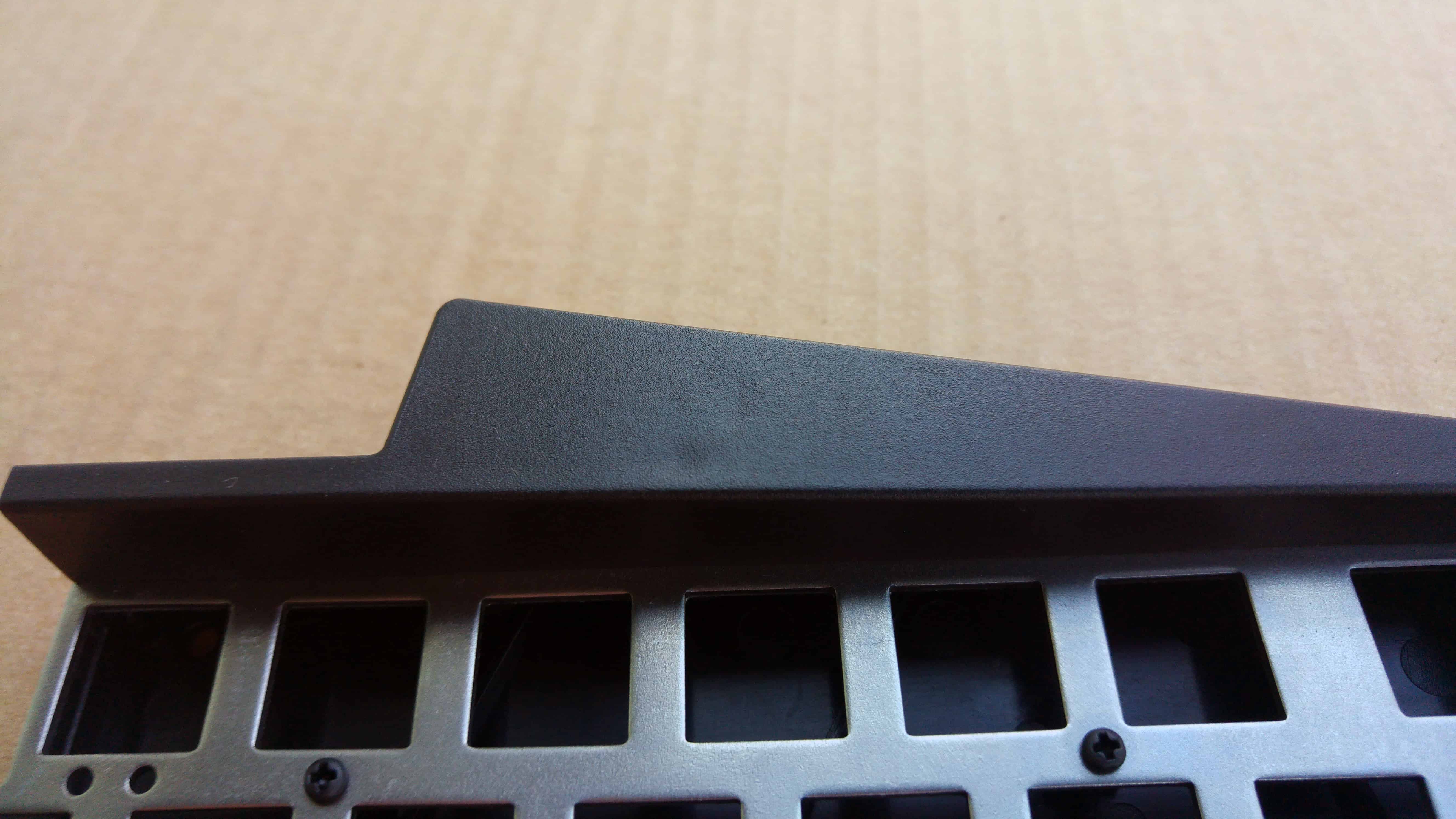
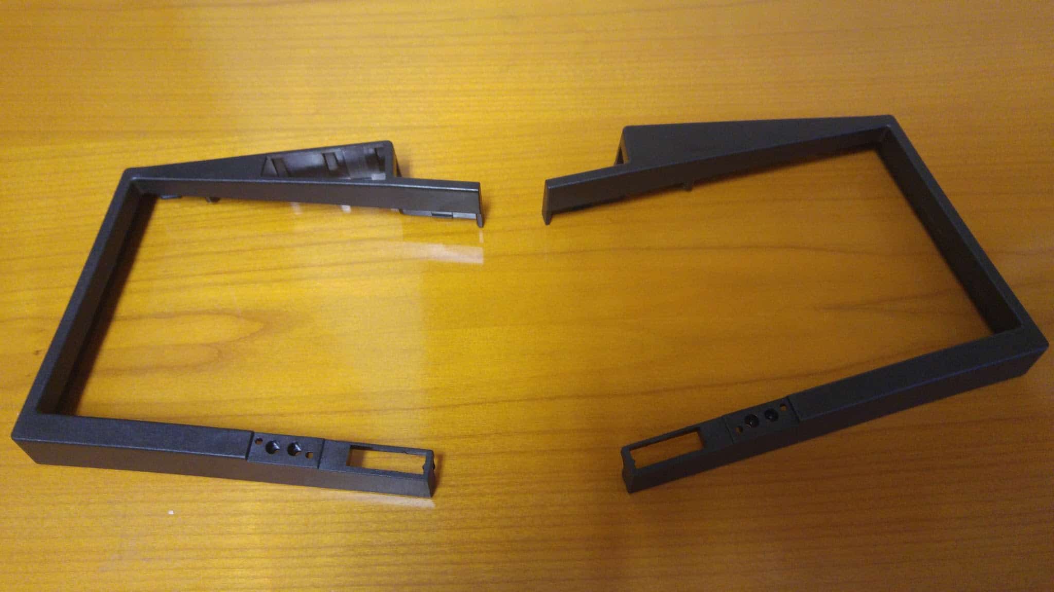
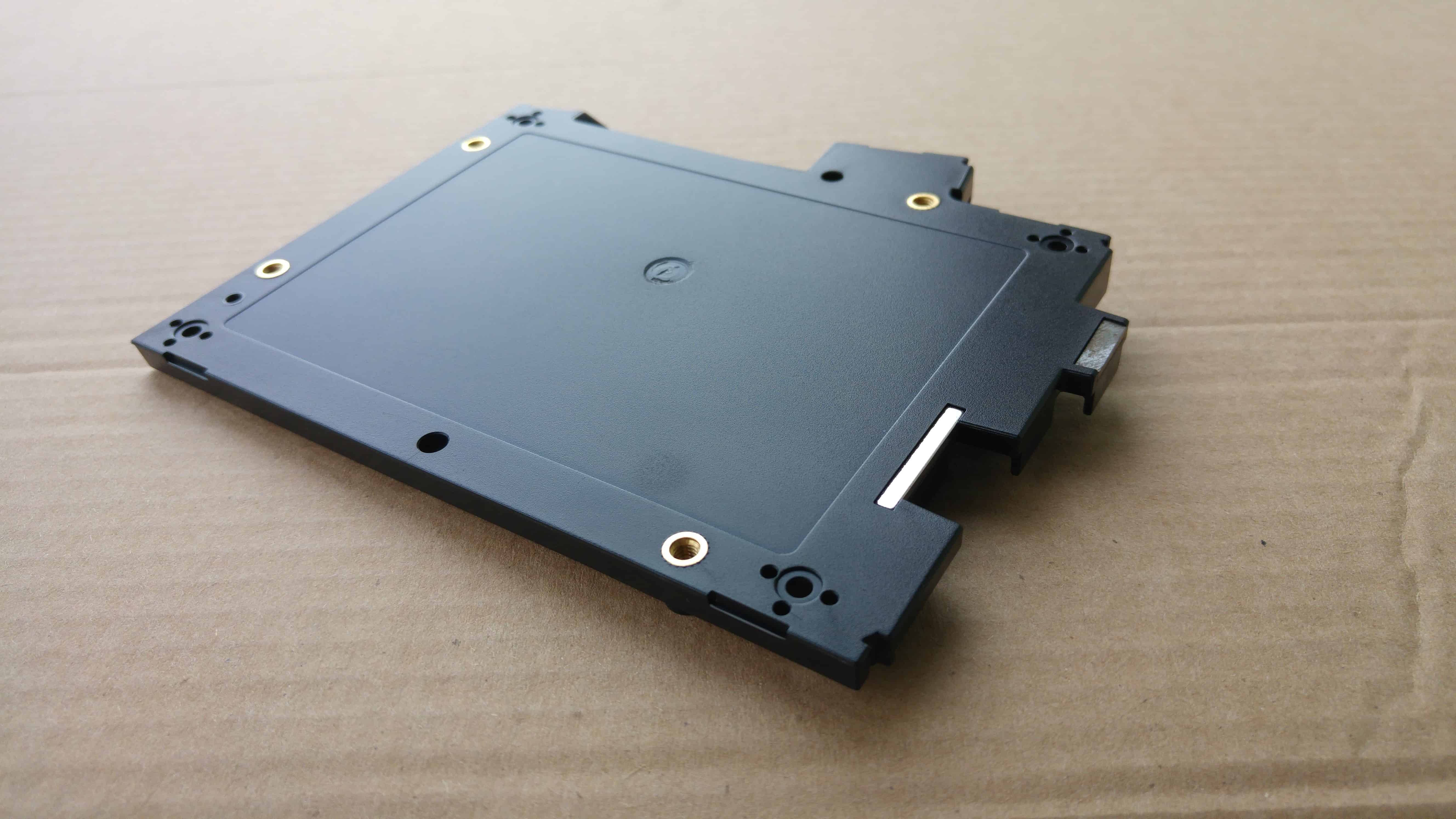
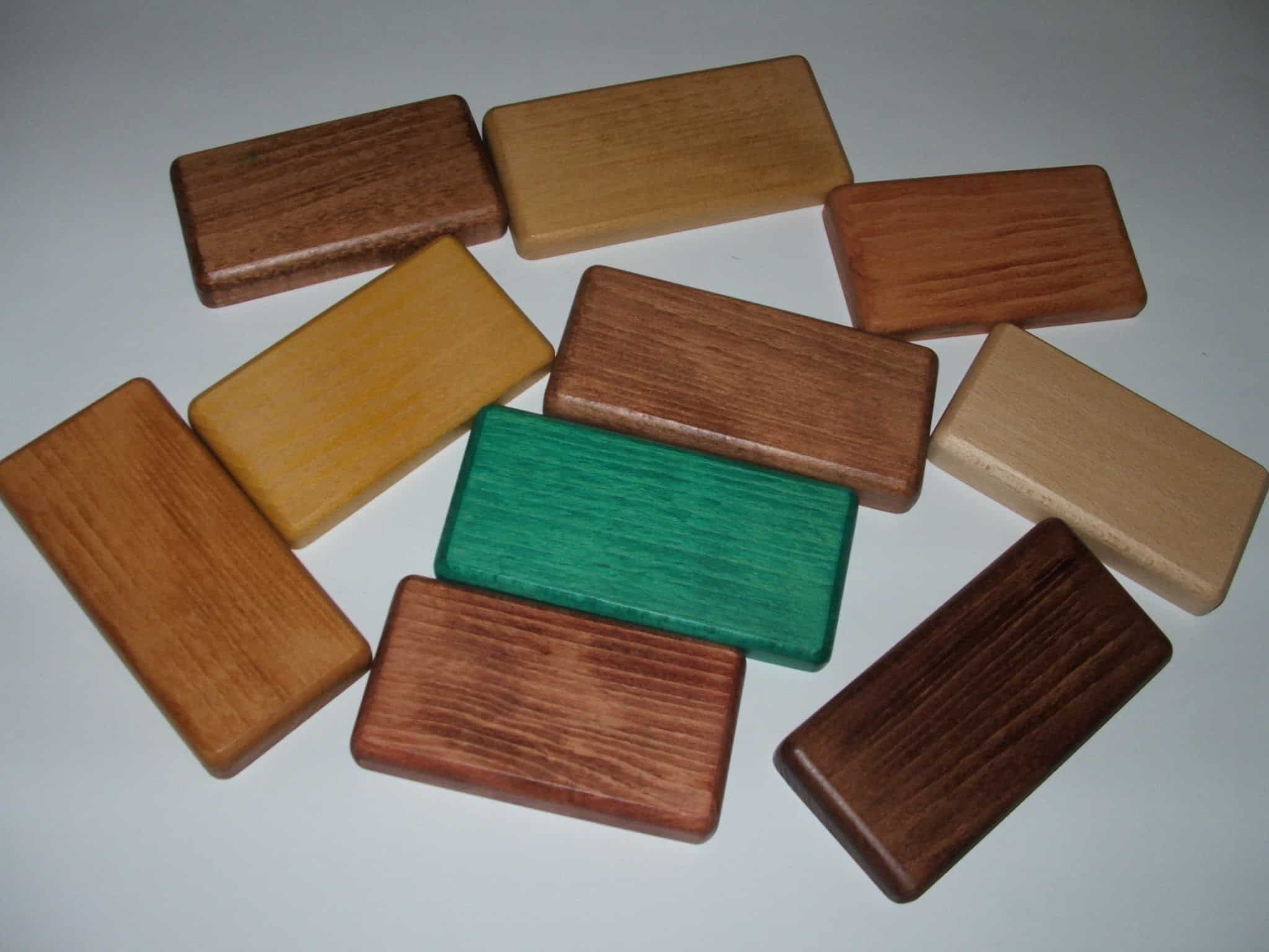
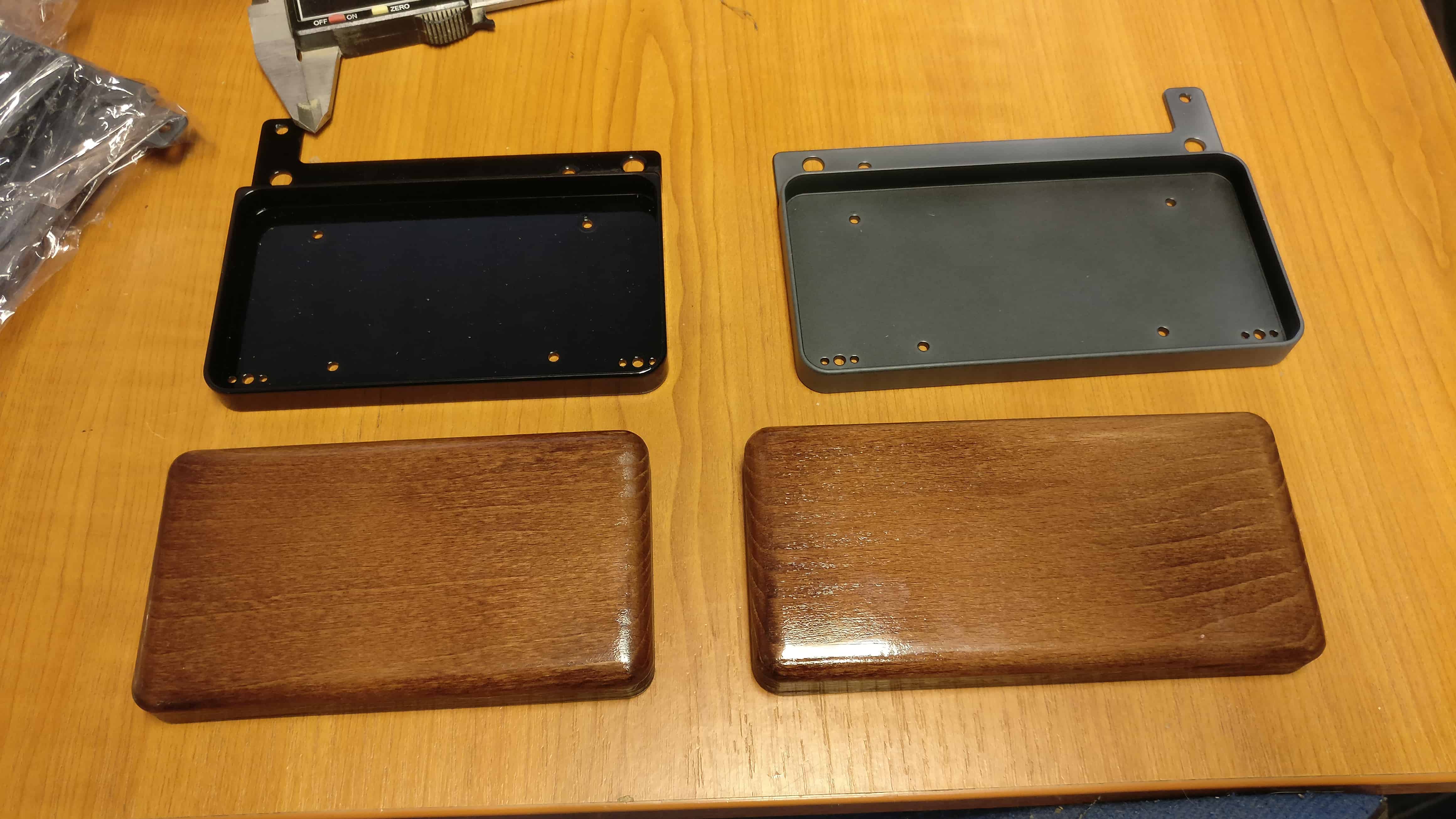
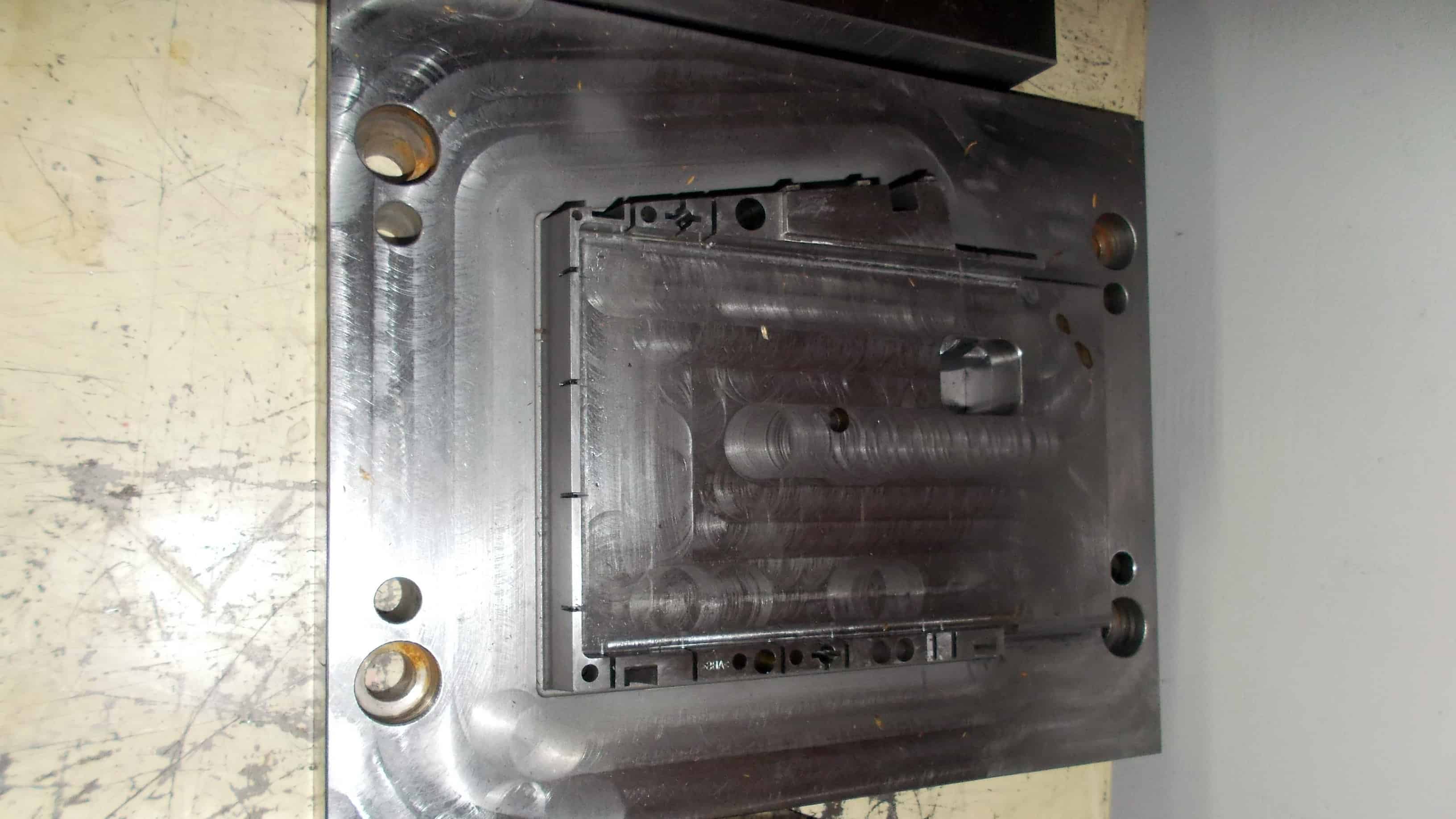
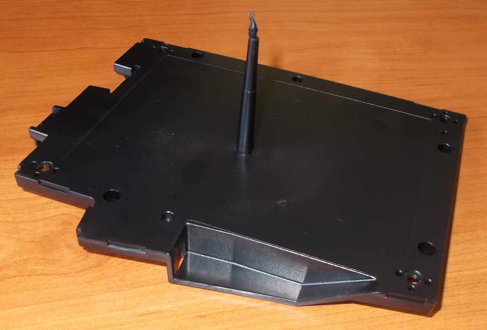
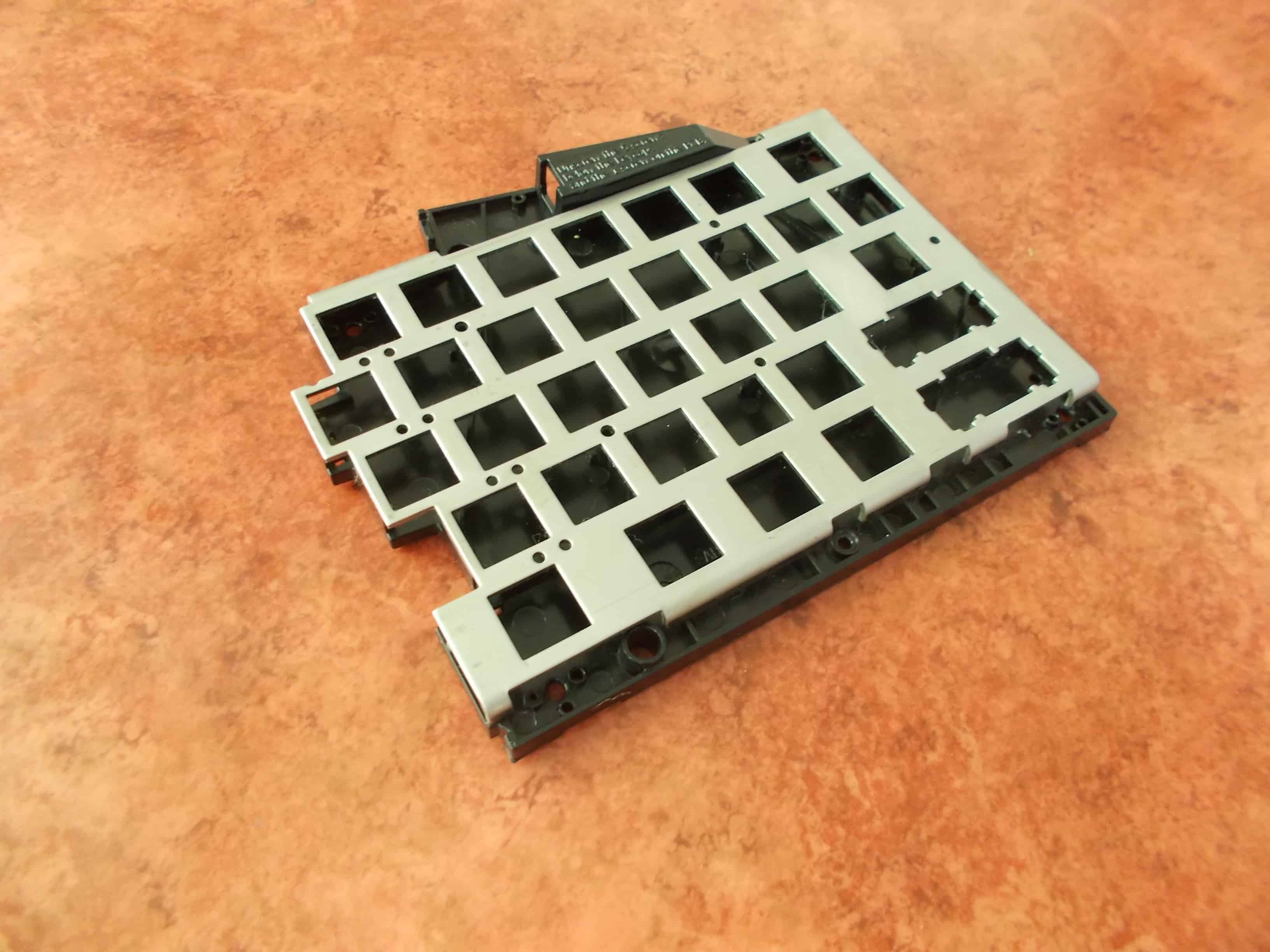
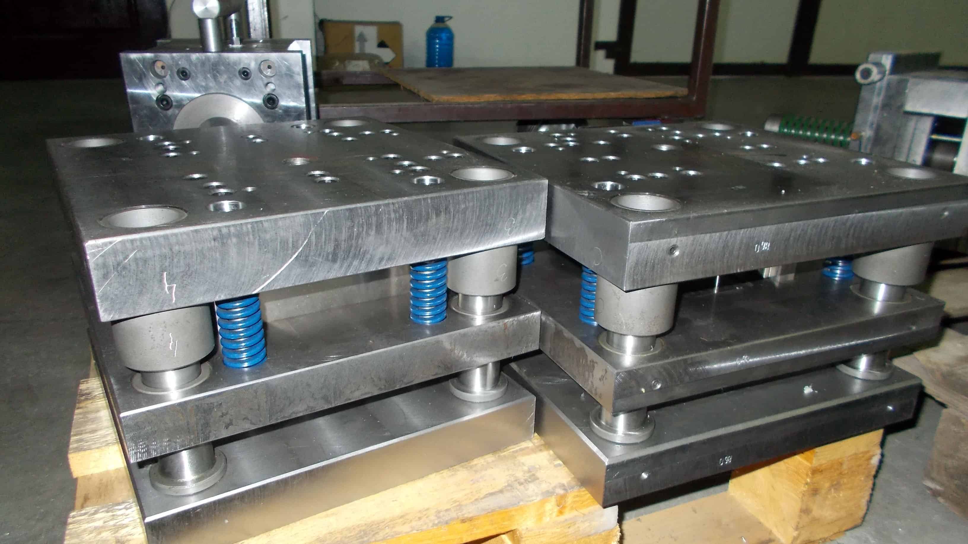
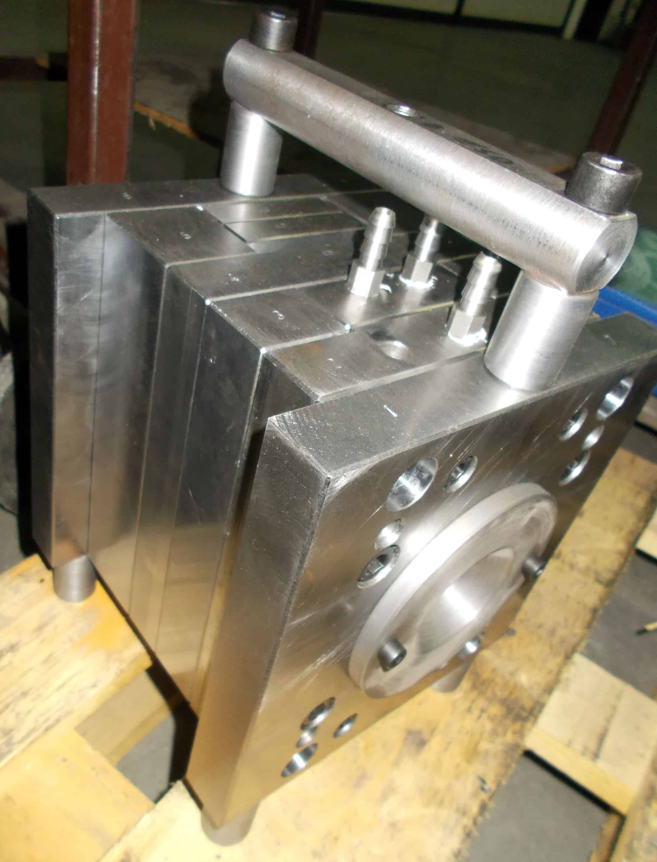
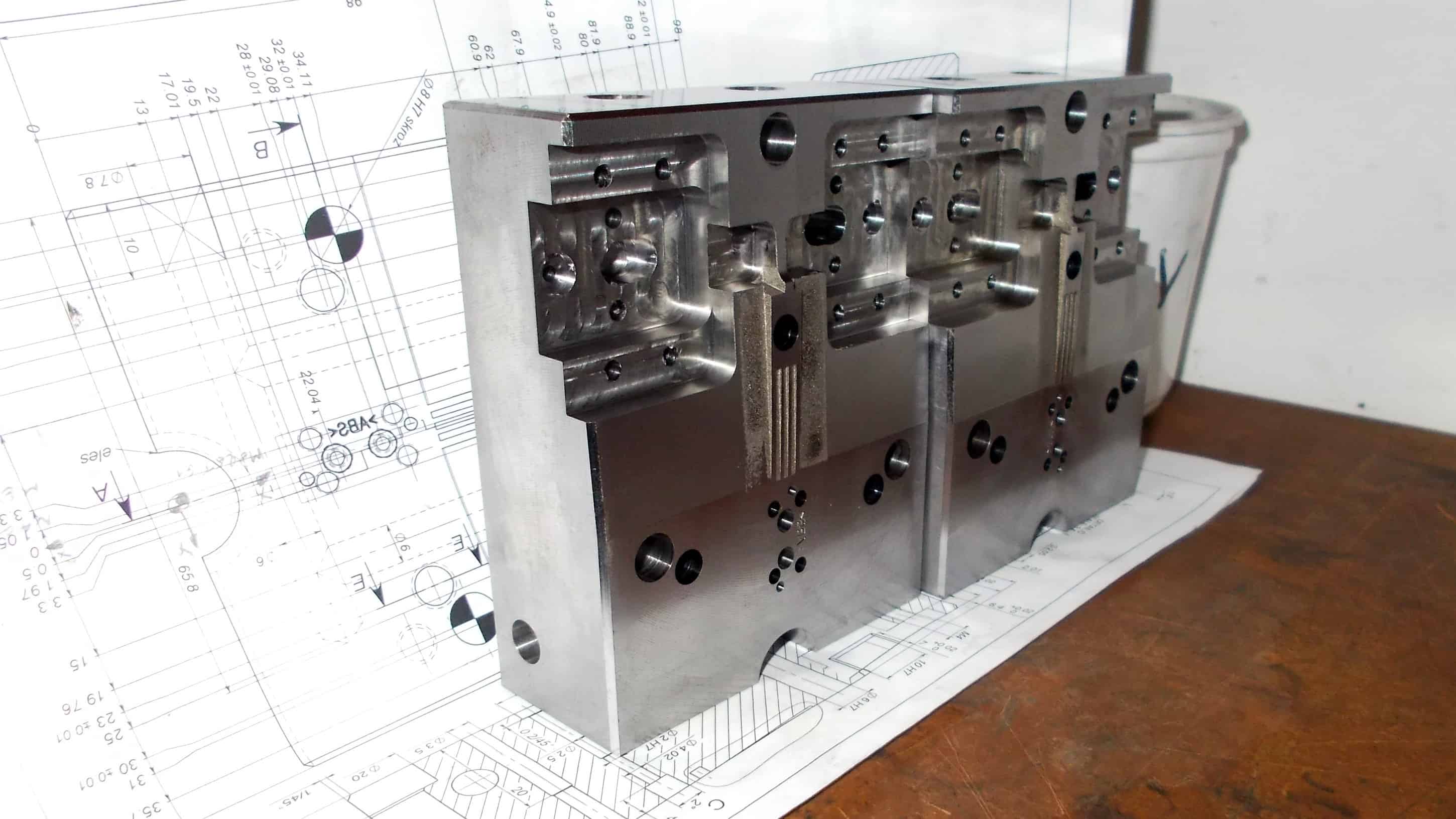
The state of the molds
Currently, the molds are being tweaked, and the tweaks are mostly cosmetic by nature. All things considered, they’re already in very good shape.
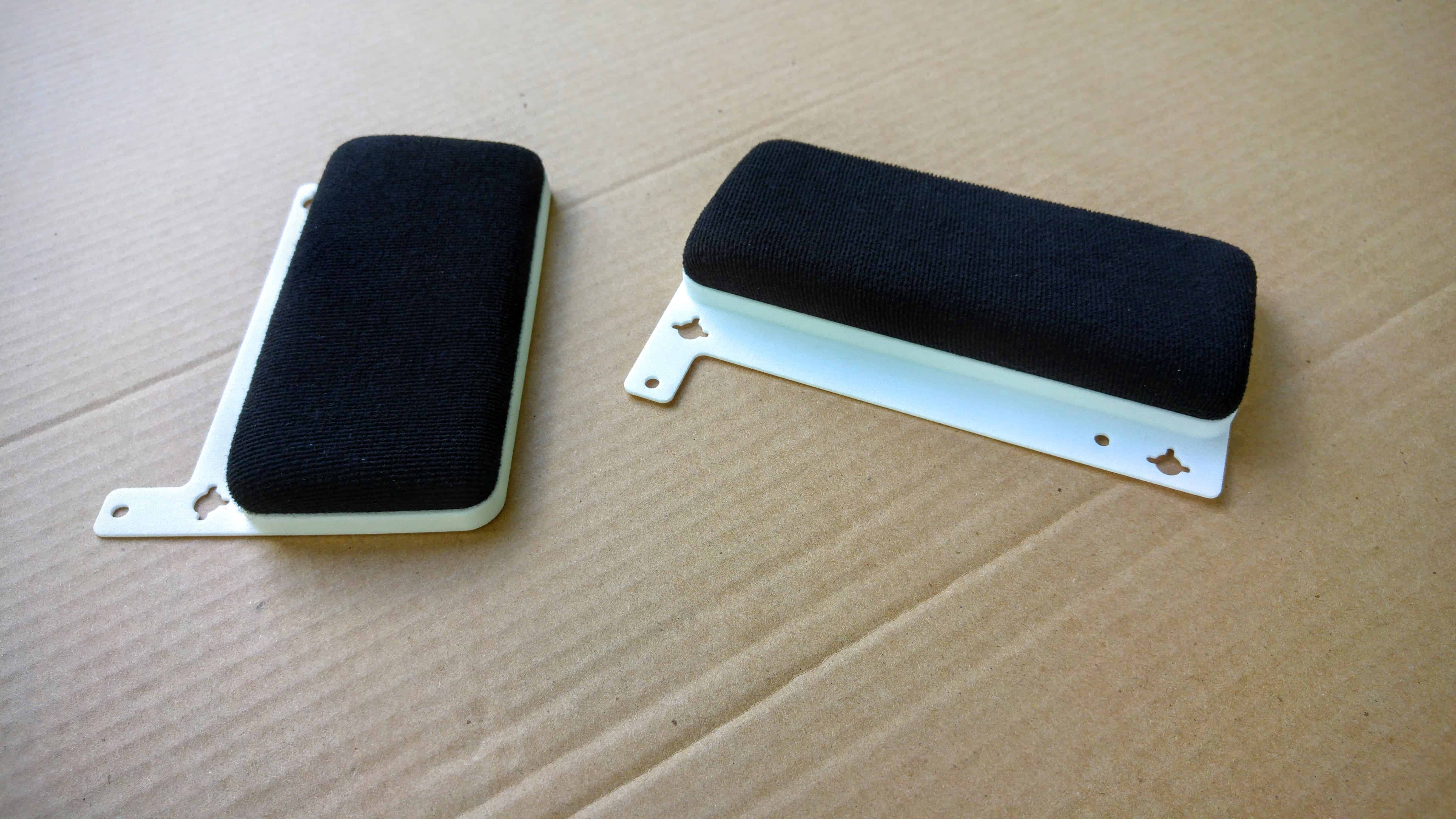
András showed the current case samples to one of his friends recently, who works for a contractor of a premium car manufacturer, and his friend was genuinely impressed by the quality of the case, so we’re already doing pretty well.
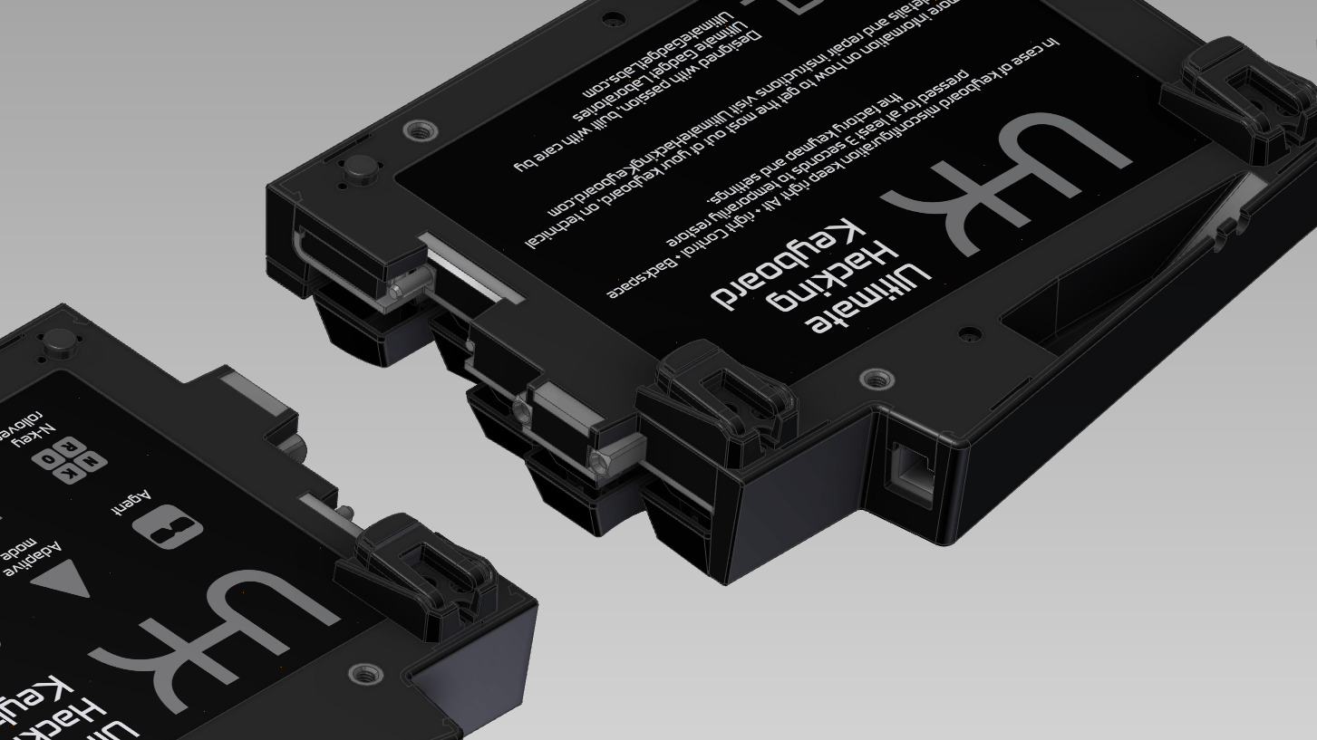
Apart from the cosmetic fixes, we also plan to add one or two snap fits to make the case more rigid when the palm rest is attached to it. These modifications won’t affect our schedule.
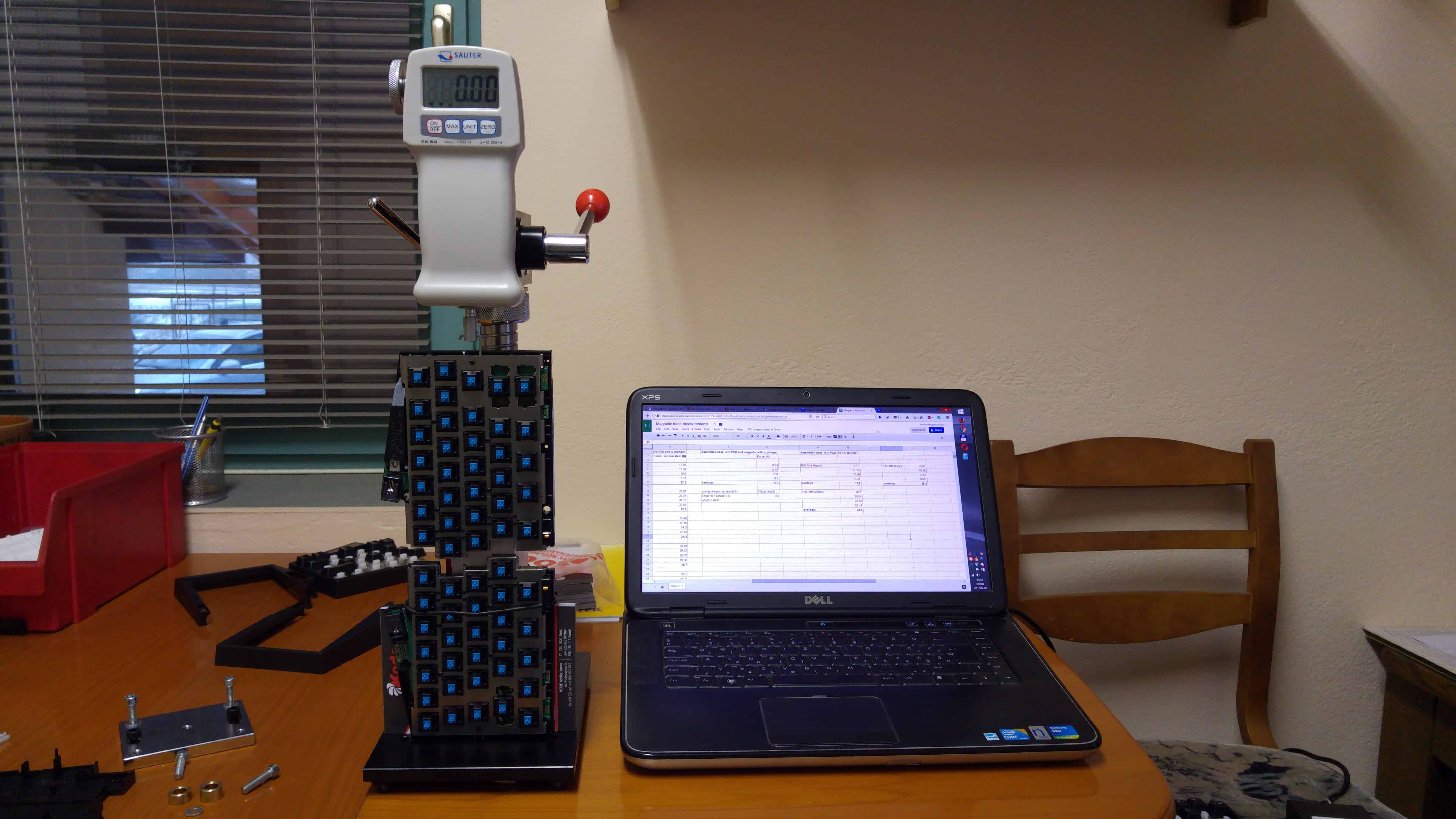
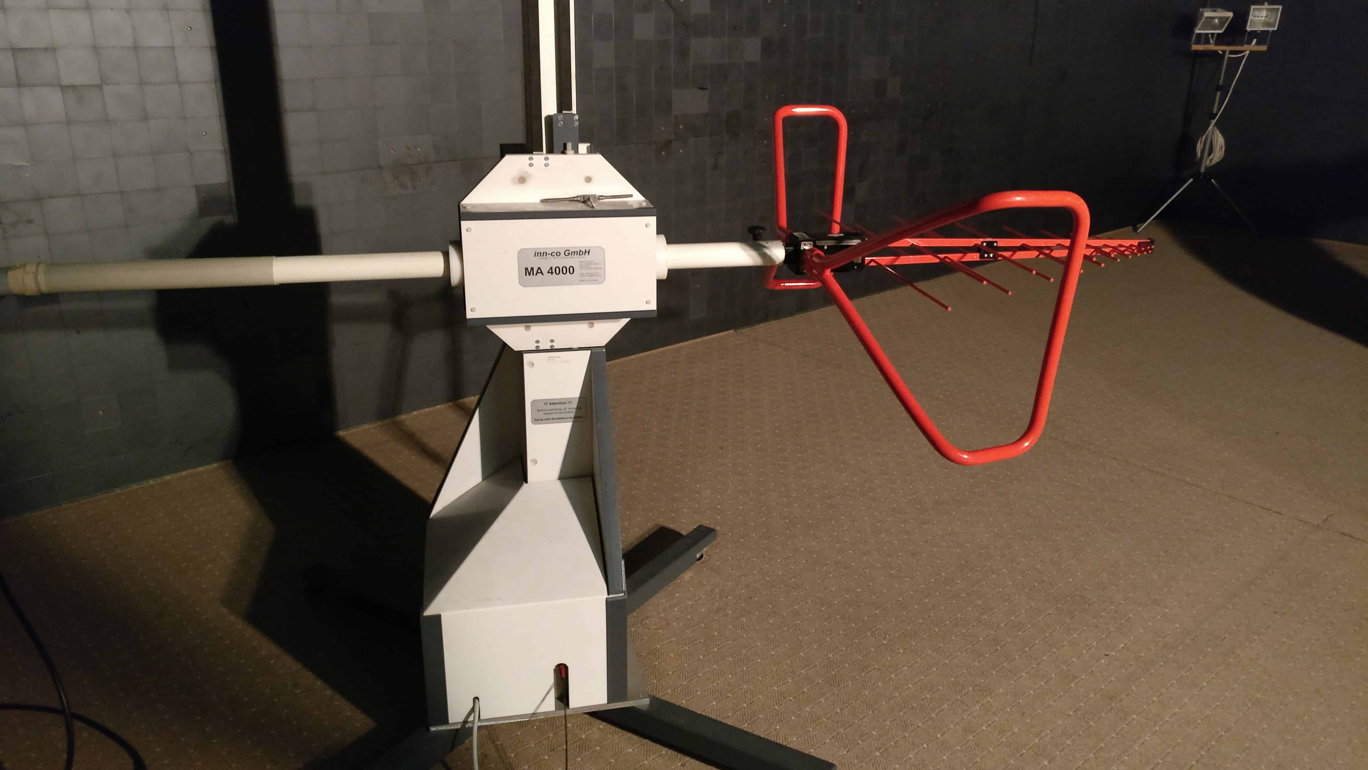
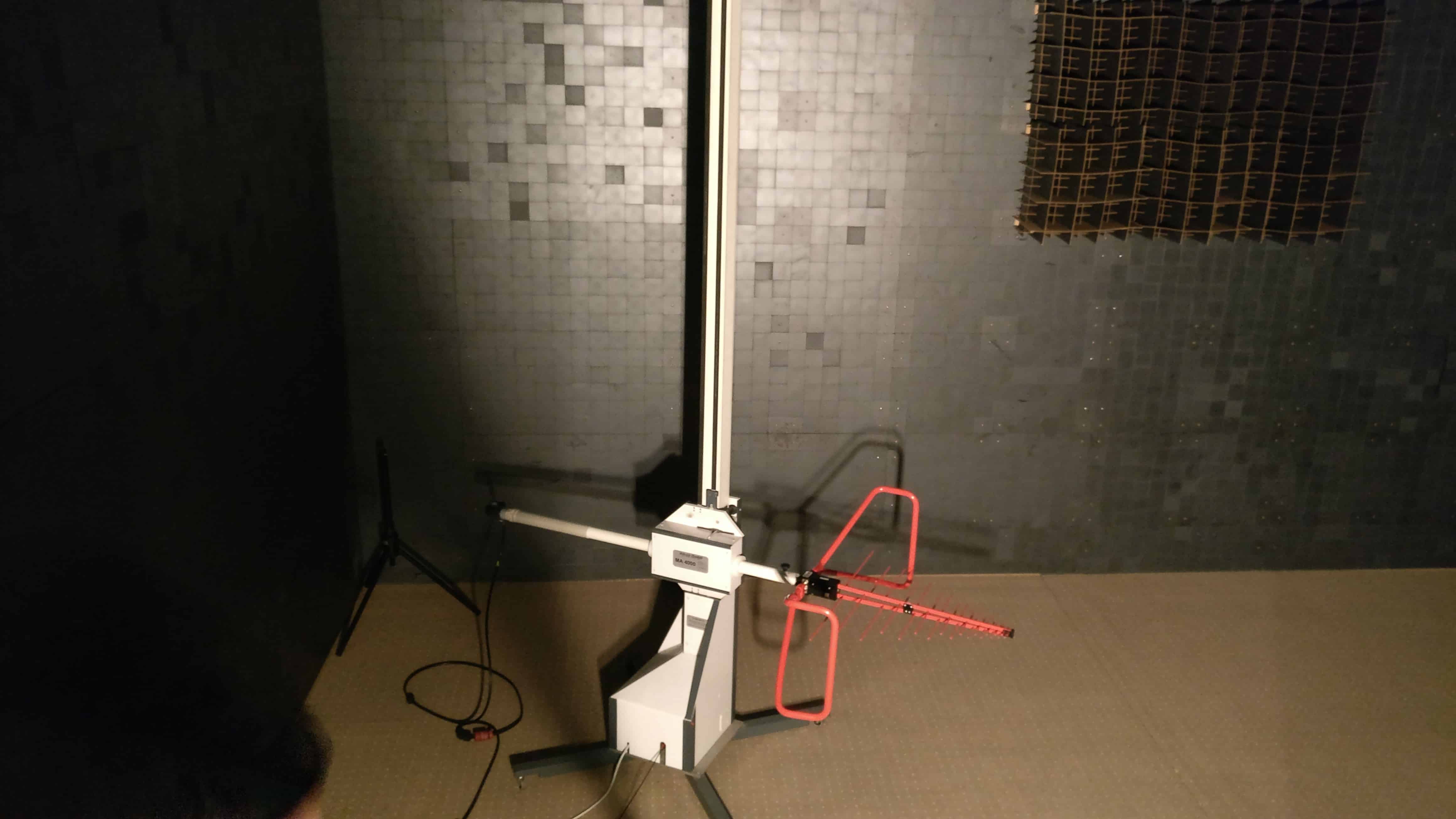
EMC testing, 2nd round
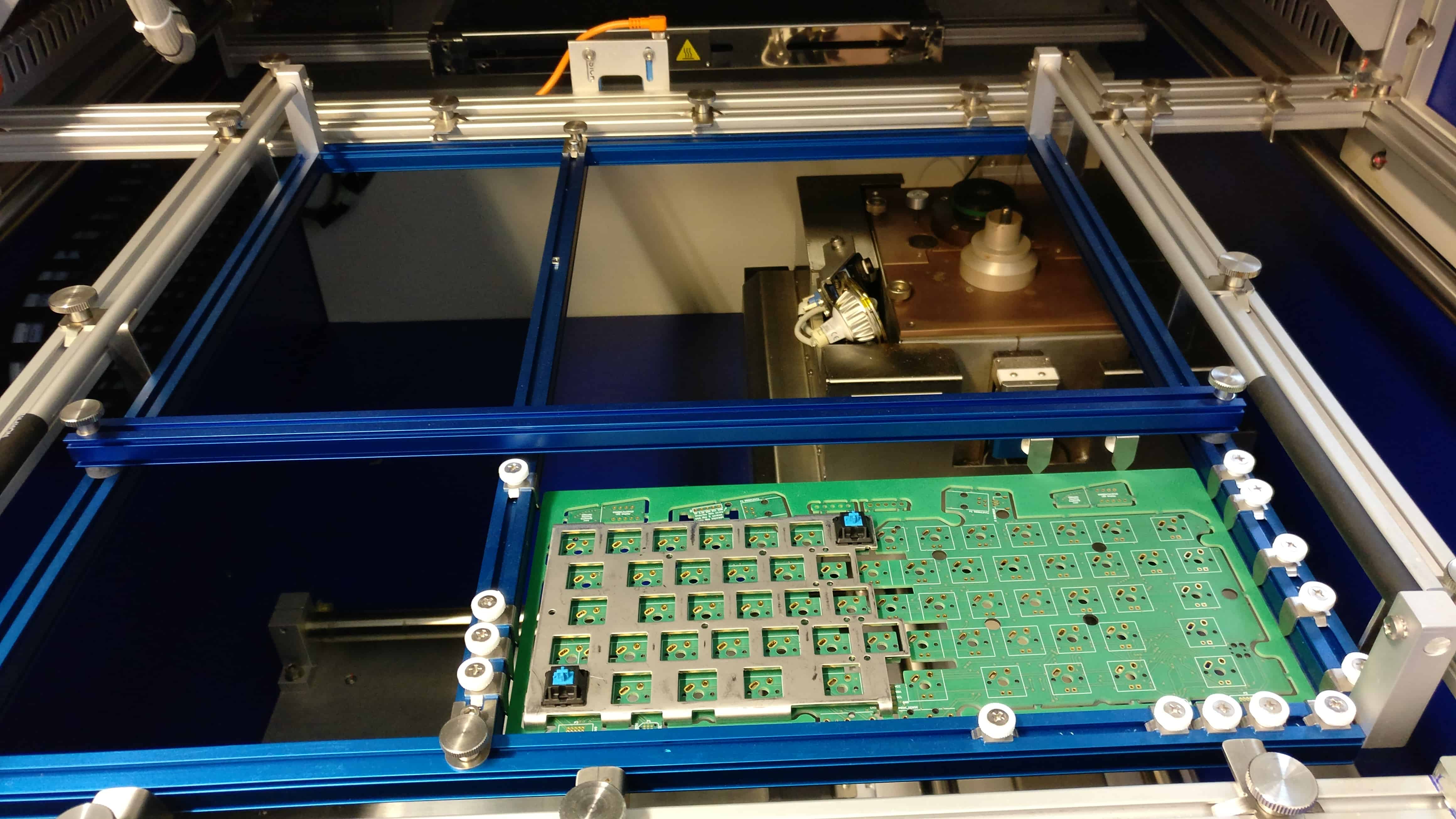
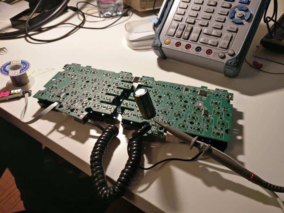
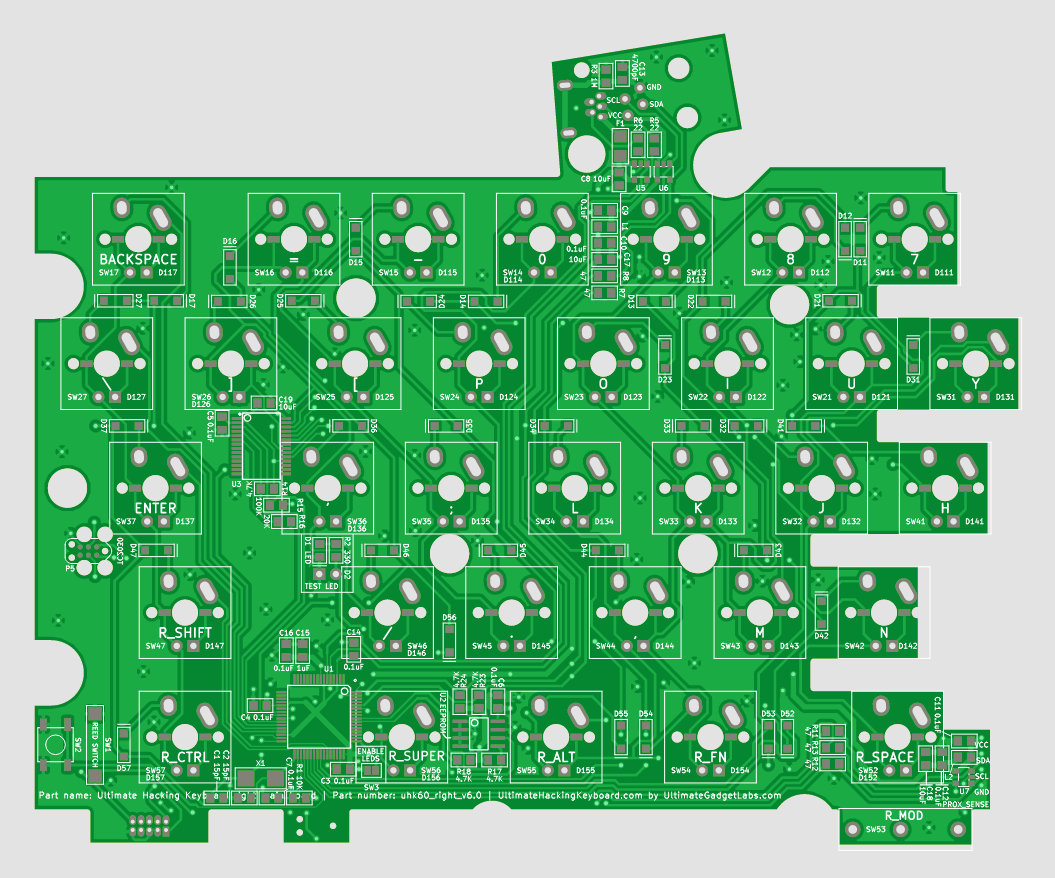
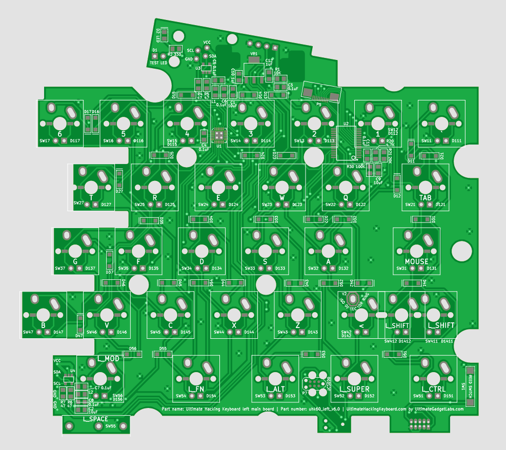
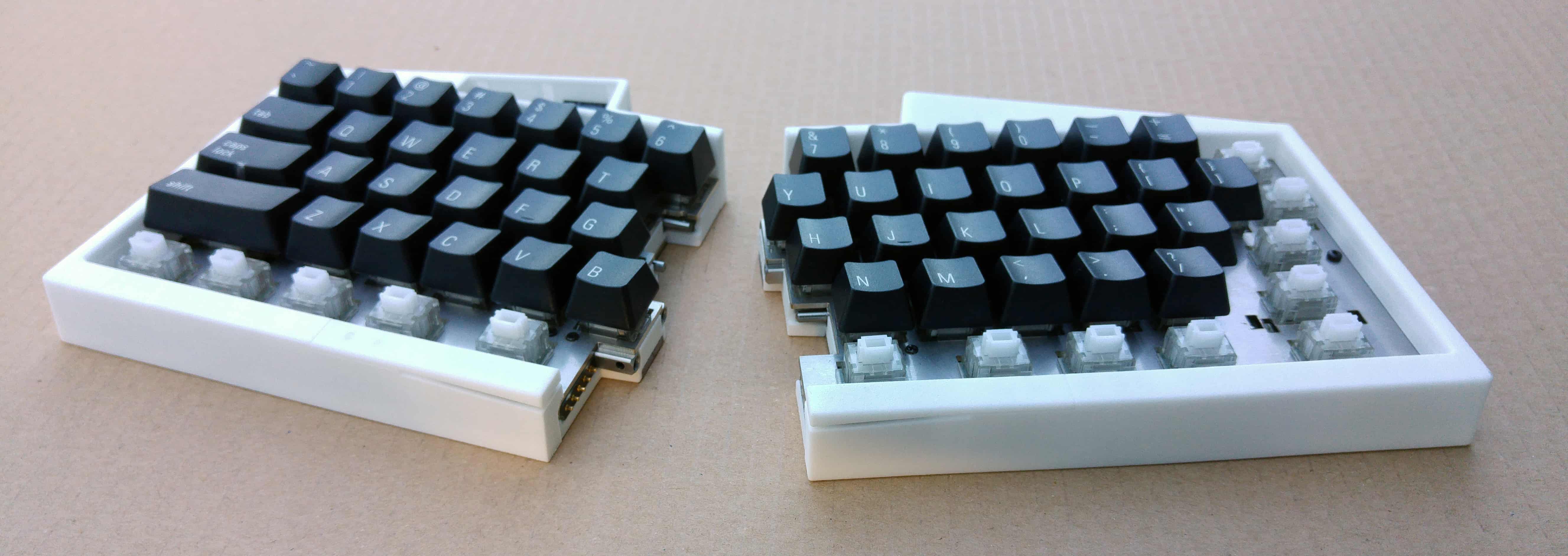
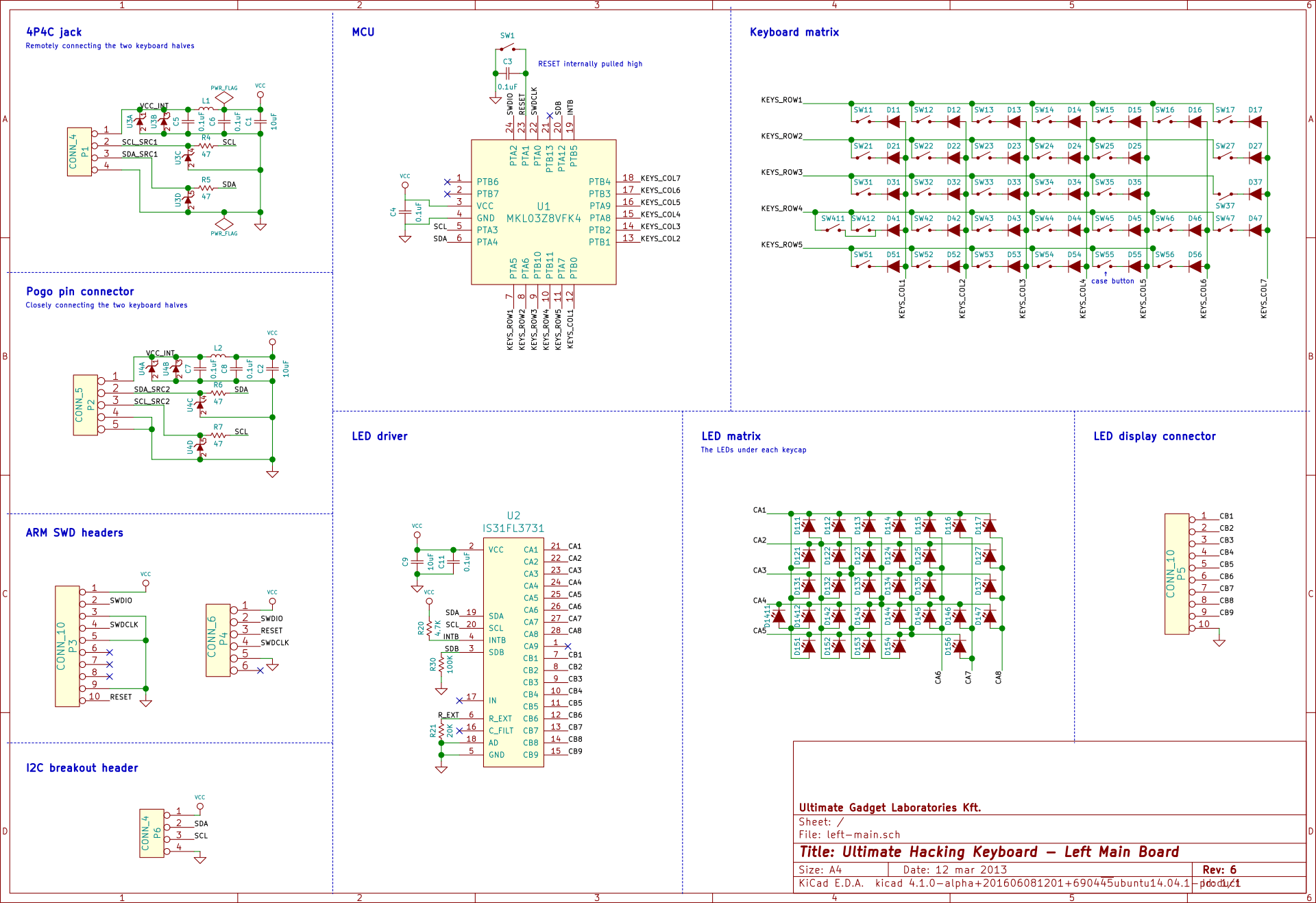
Here we go again. Since our last update, we’ve created new prototypes to be tested in the EMC lab.
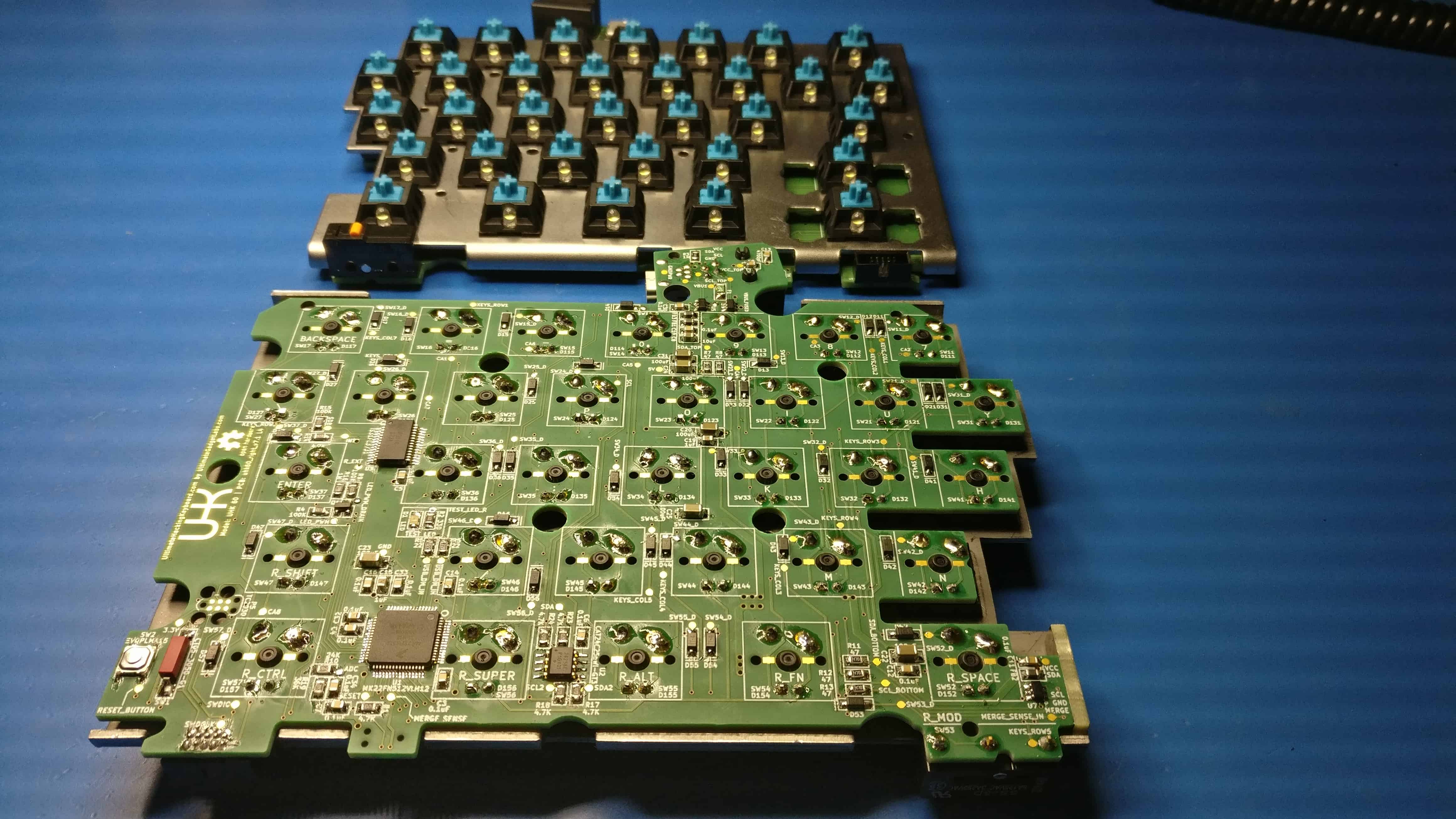
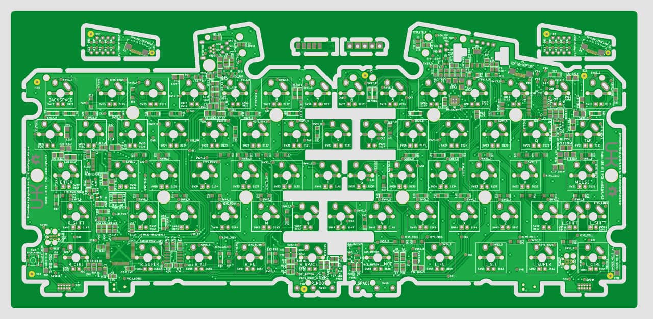
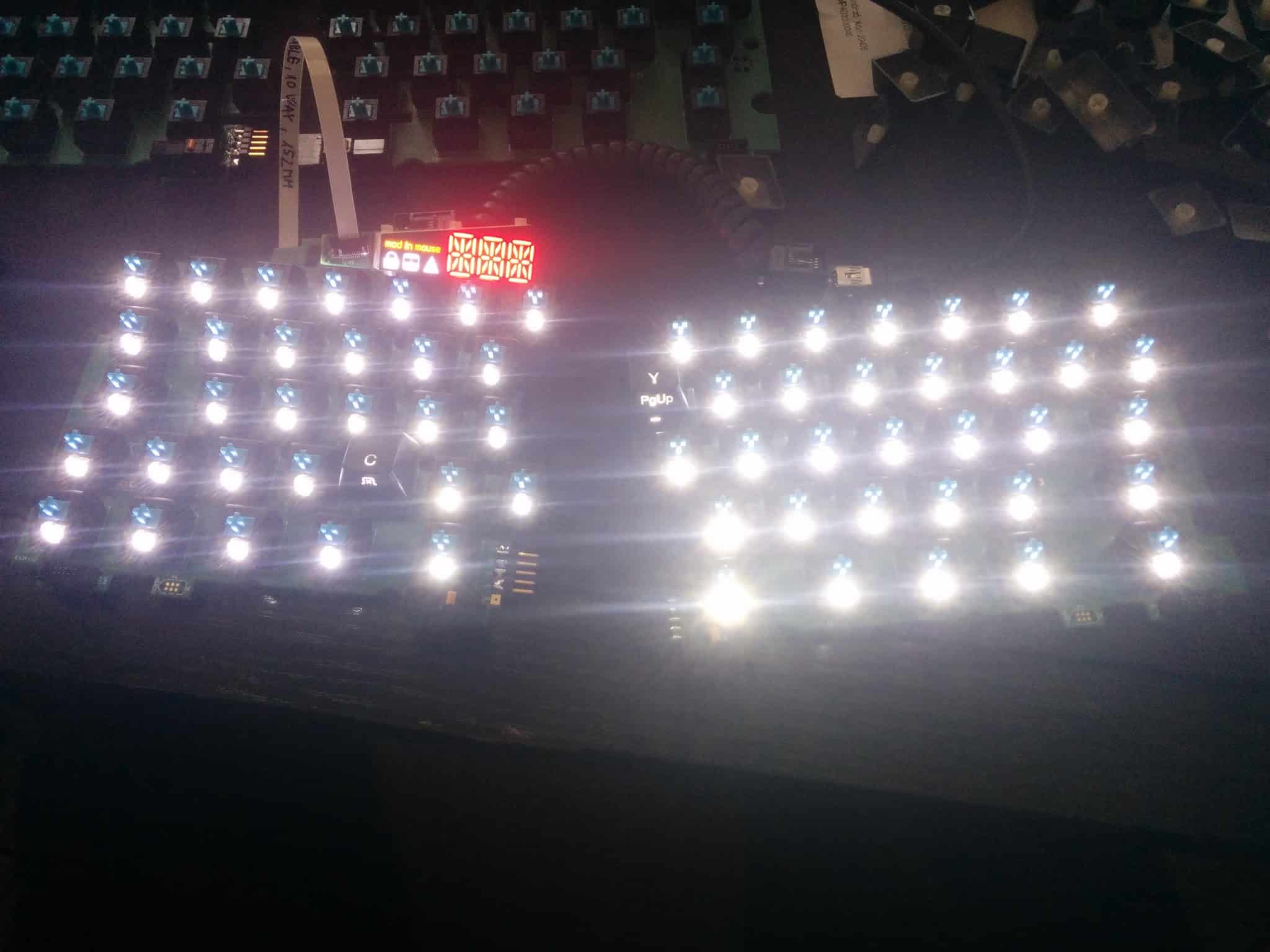
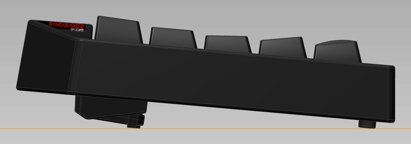
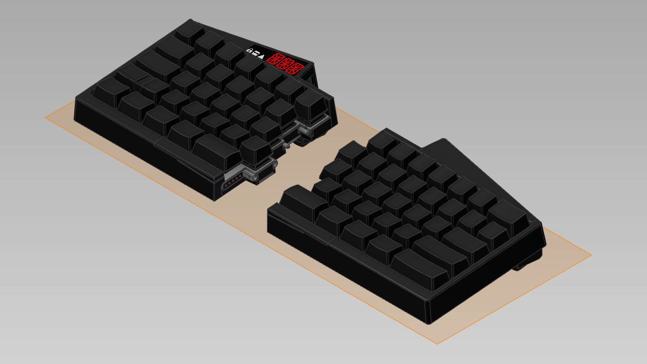
These are actually two right keyboard halves. The left keyboard half hasn’t been redesigned because, according to our tests, the USB is the major culprit when it comes to EMC issues, which are located on the right half.
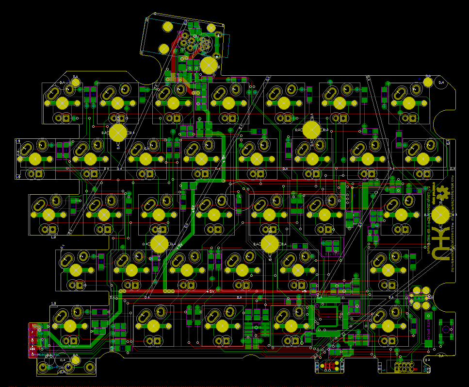
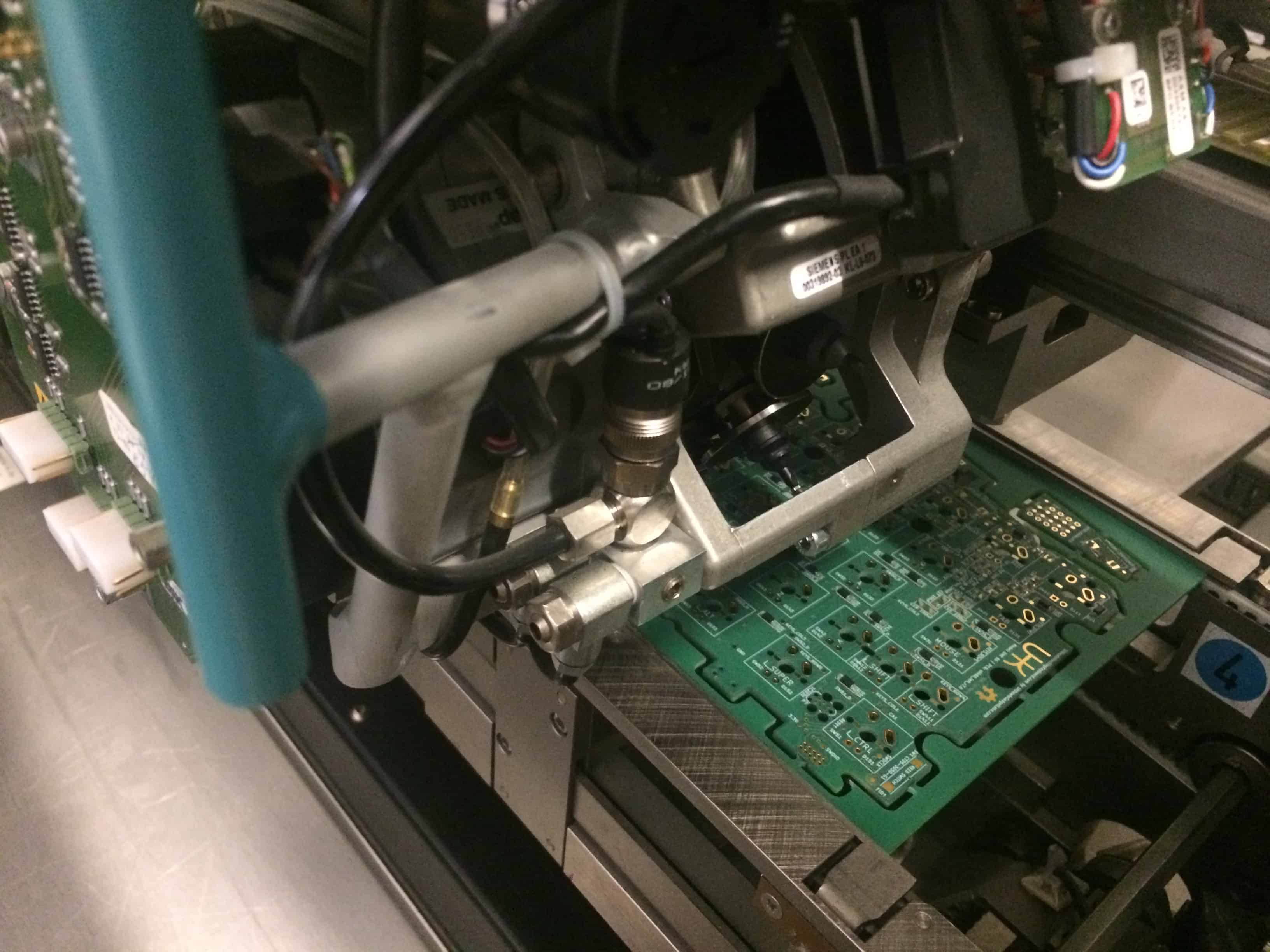
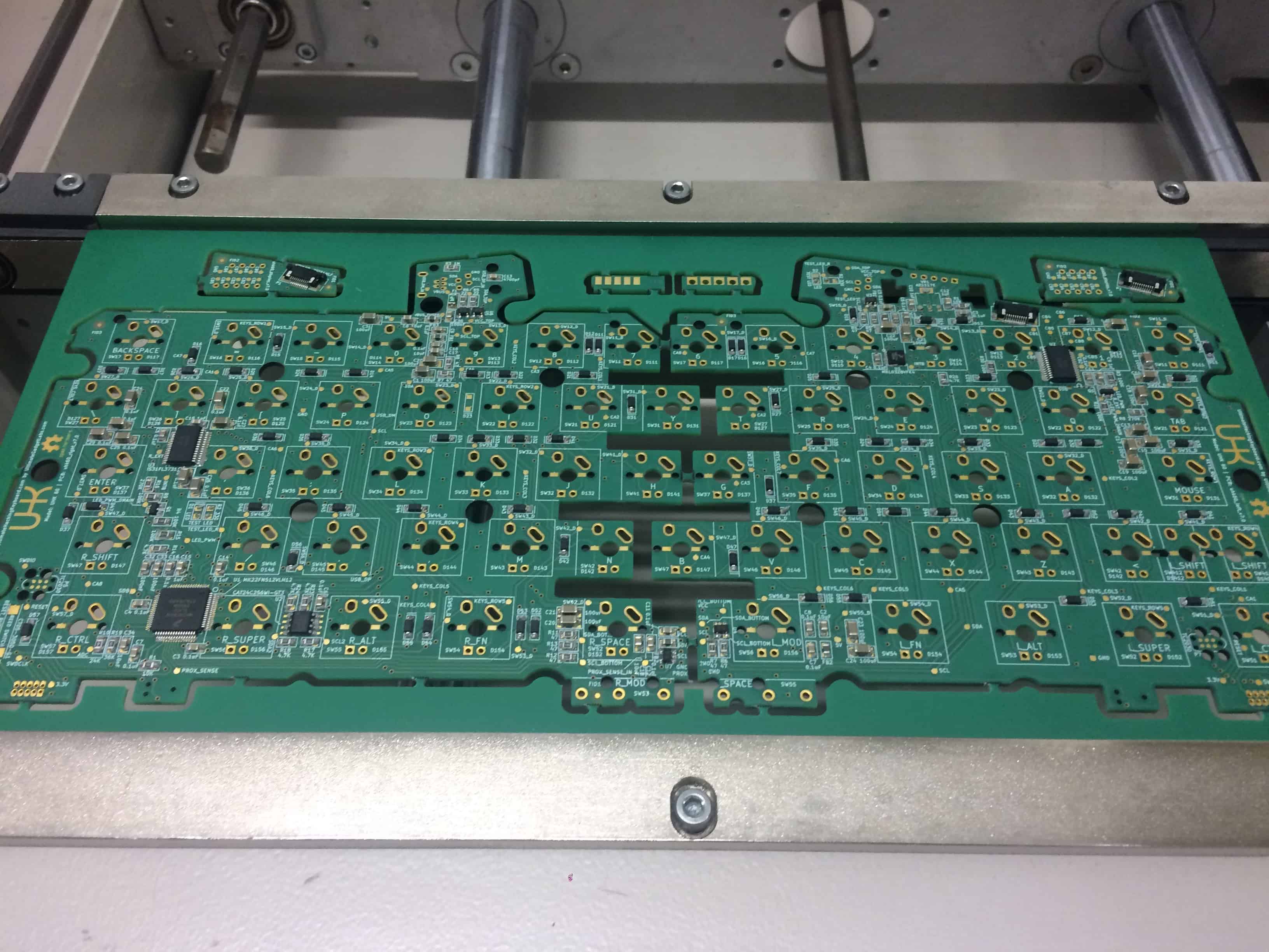
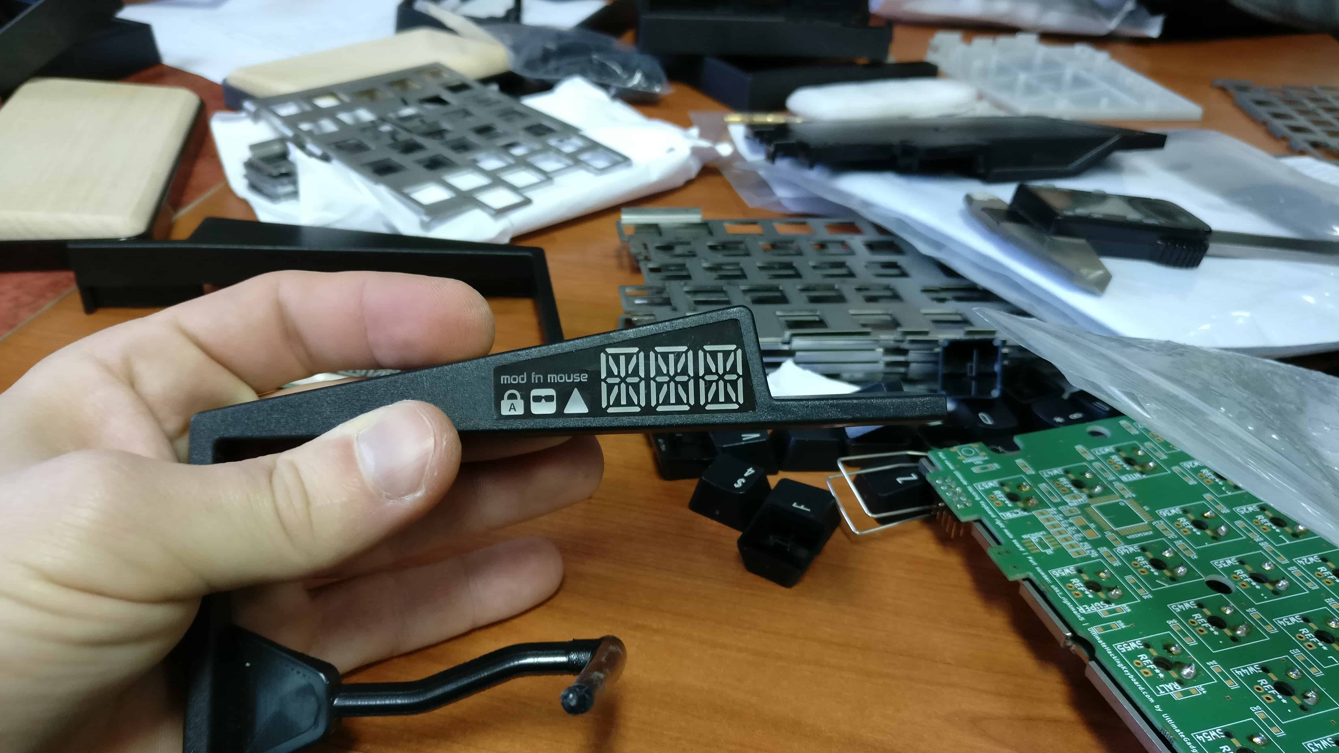
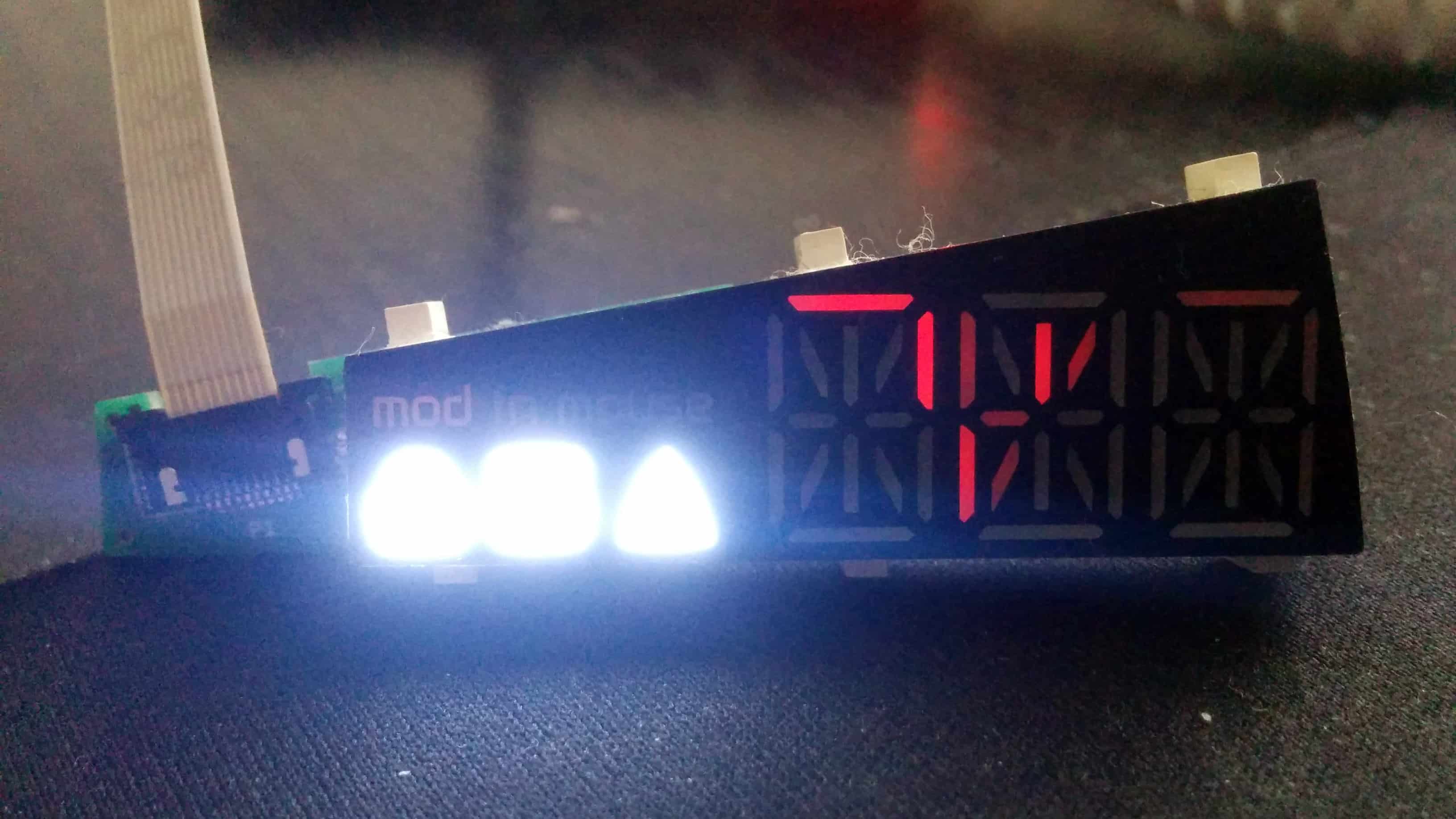
We were told that a 4-layer PCB should perform better when it comes to emissions than a 2-layer one, so I decided that we should create both a 2-layer and a 4-layer PCB and see how they stack up.
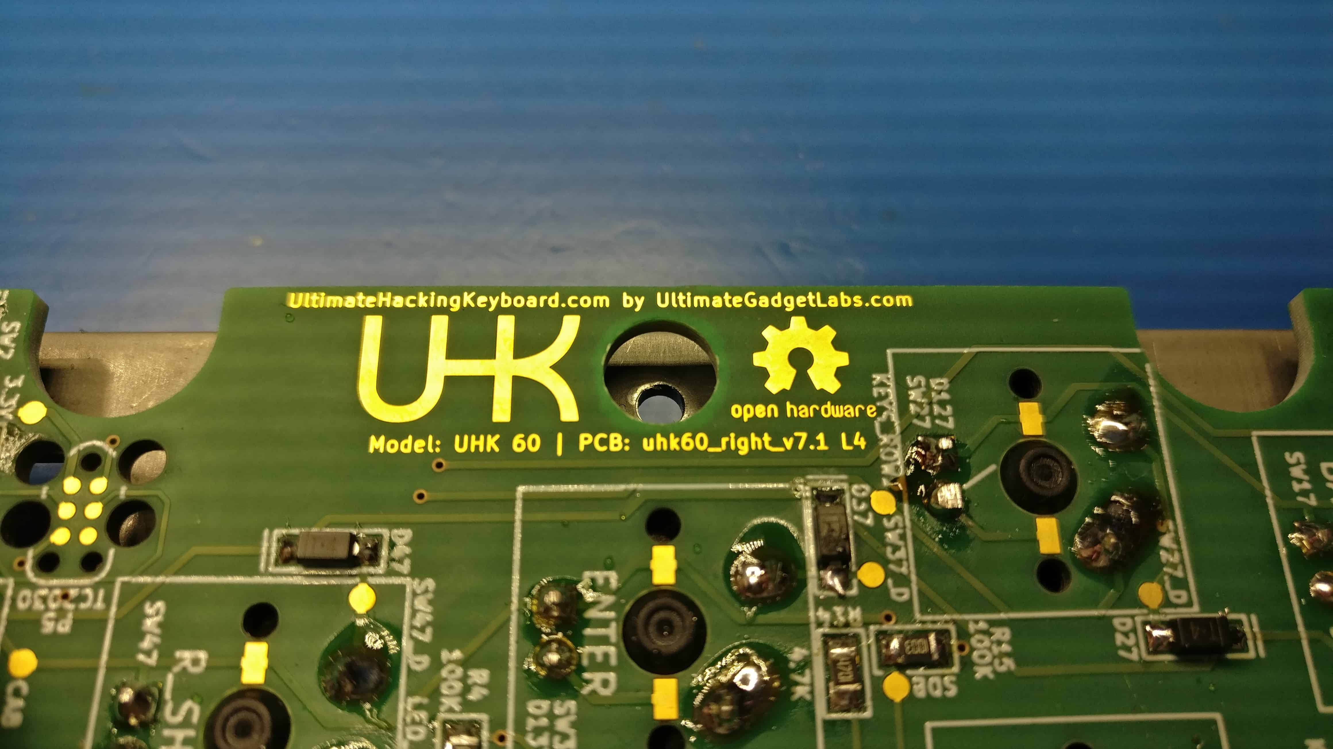
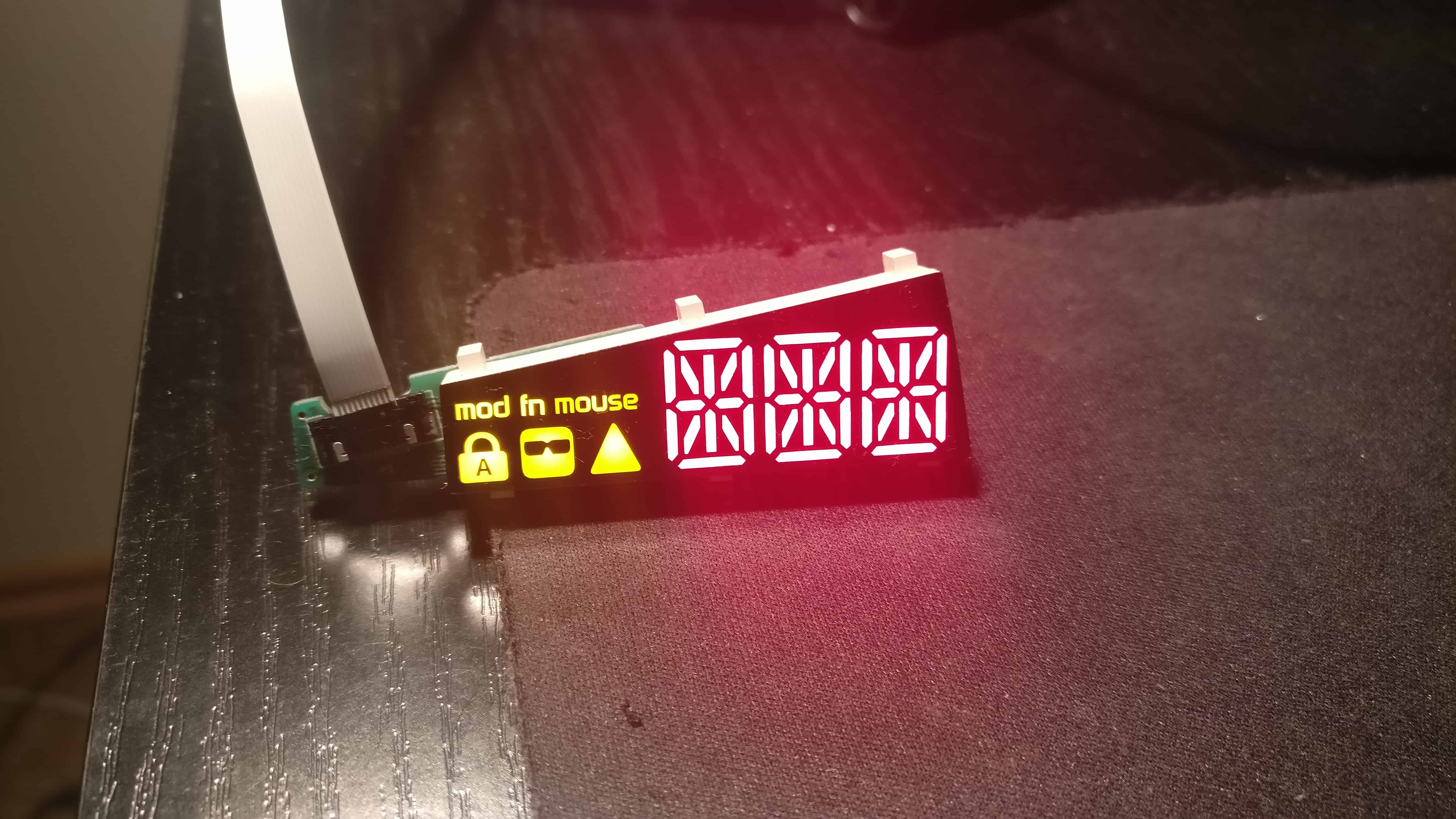
The naked eye can hardly tell the 2-layer and the 4-layer PCBs apart, so I put an “L4” identifier right after the PCB identifier text for the 4-layer PCB. Now it’s easy to tell.
Even though my hopes were high that we’d pass the tests with the new boards, I prepared for the worst and was looking for expert help. That’s how I found Endre Köcze.
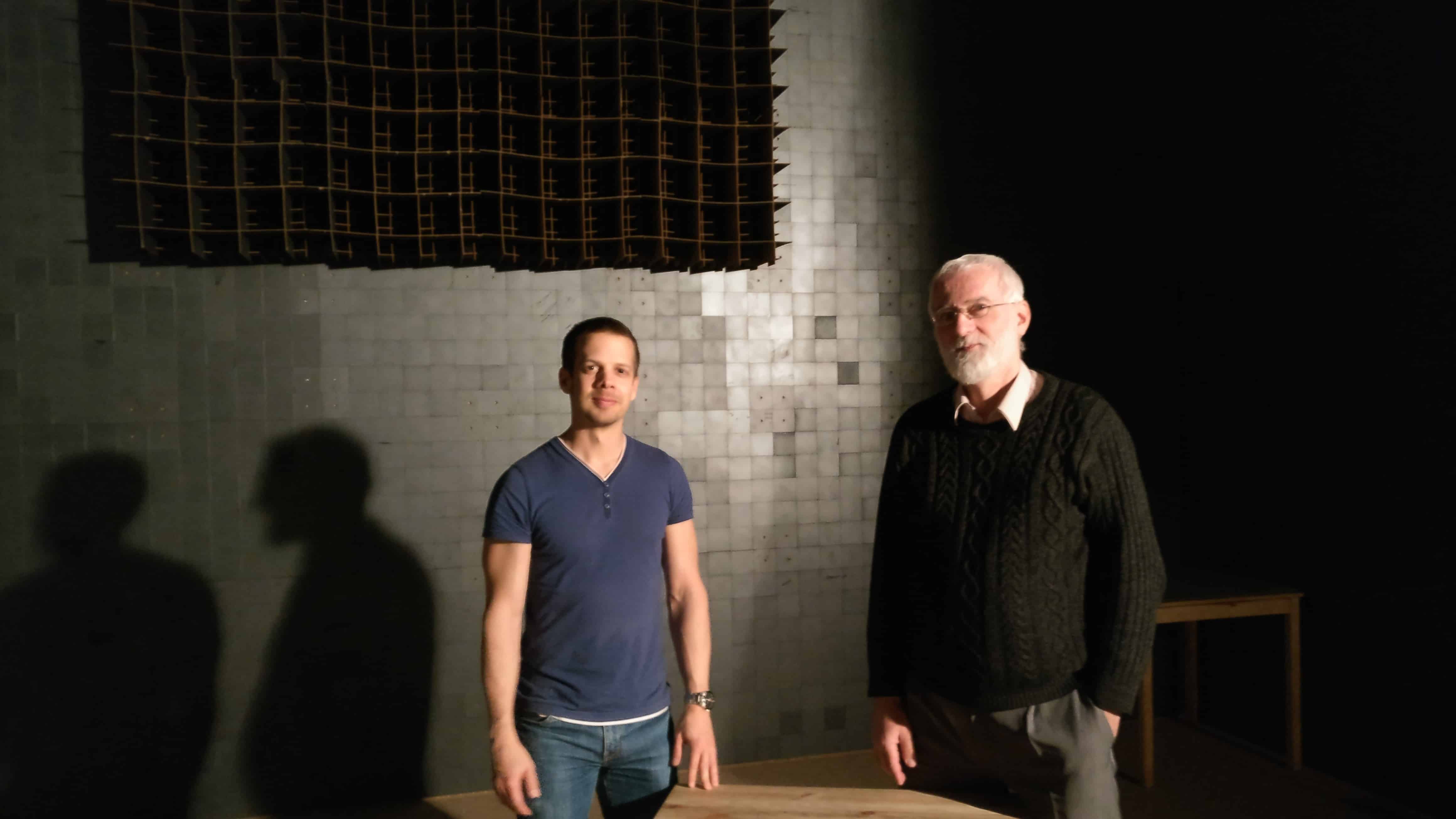
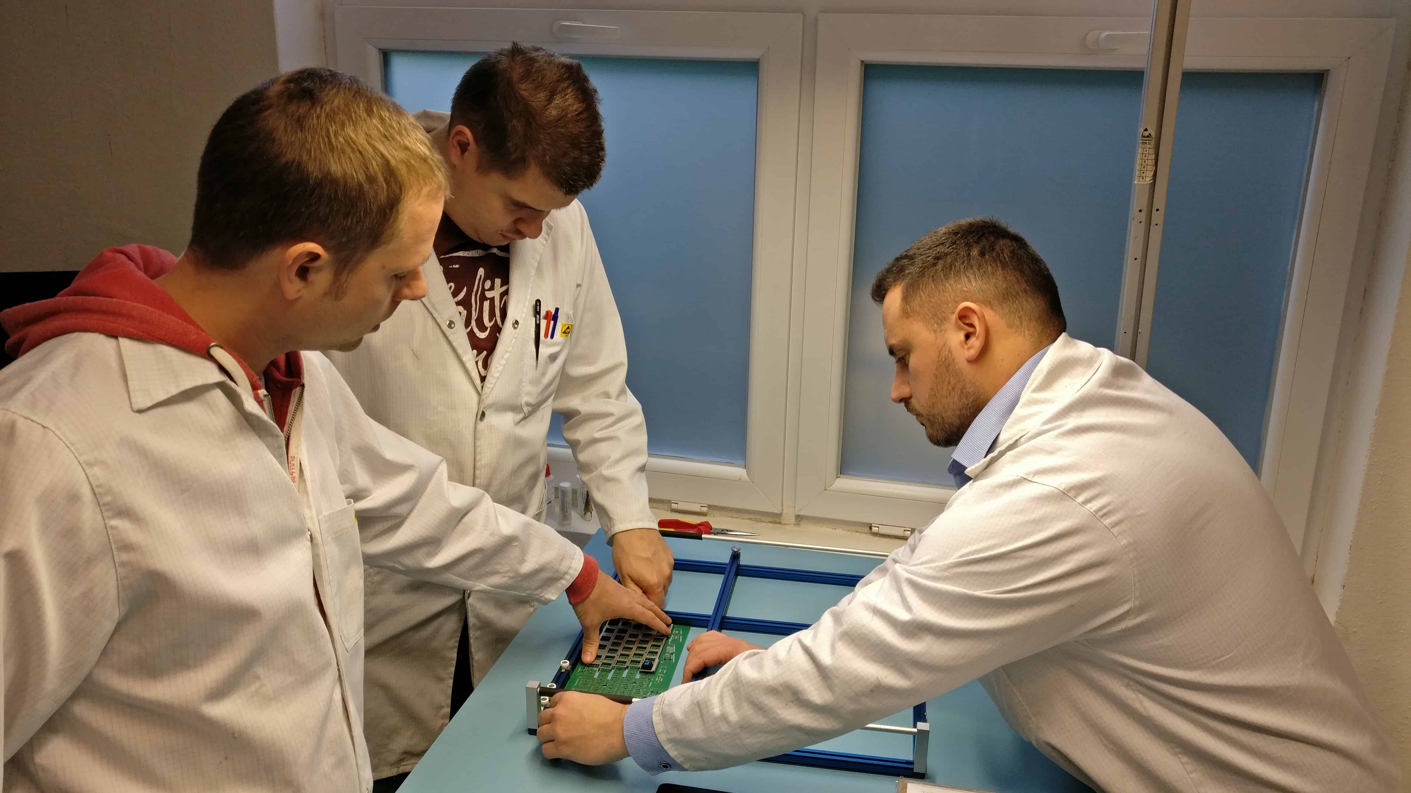
Endre has a lot of experience behind him as an electronics engineer, and he’s a pleasure to work with. He has taken a thorough look at the UHK design, and we went to the EMC test together.
The test results started off as quite a surprise. First, we measured only the laptop as a reference point, and according to the measurements, it didn’t pass! Go figure.
Previously, we used Robi’s laptop, which passed the test with flying colors. This, however, was Anna’s, my wife’s laptop. Admittedly, this laptop is not as fancy as Robi’s laptop, but a reputable manufacturer makes it, and it should also pass the test.
The first takeaway is that we’ll bring as many laptops as we can next time, pick the least heavily emitting one, and use it in further measurements.
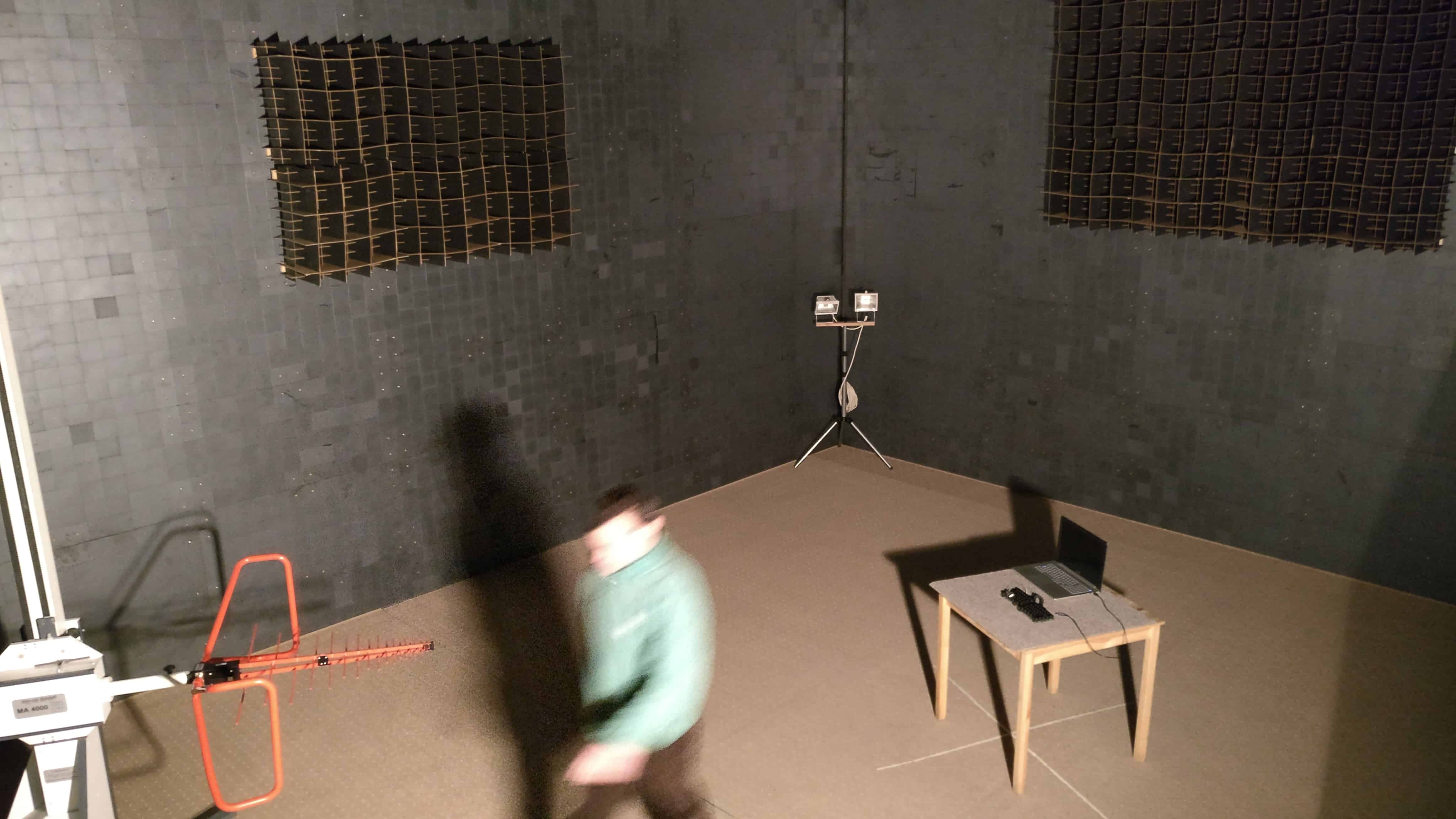
Next, we put the laptop under the measurement table, and then its measured emission got just below the red line. But when we added a shielded USB cable, even with the ferrite on the host end, it went just above the limit. This is clearly not ideal, but this is the best we could do on the spot. The measurements are still useful, and we’ll use a better laptop next time.
In this setup, the UHK was on the table, which is the center of measurement towards which the antenna points. Being under the table, the laptop didn’t affect the measurements so much. Next time, we’ll probably use a 5-meter-long USB cable and put the laptop as far as possible.
Around the end of the measurement, the OS shut down because the battery was so low. We could still use the laptop without the OS running, but both the low battery state and the fact that no OS was running might have affected the last four measurements. The lesson here is obvious: Power the laptop from a damn charger! And on that note, we’ll probably put the charger as far from the center of the measurement as possible, too, and use an extension cord to power it.
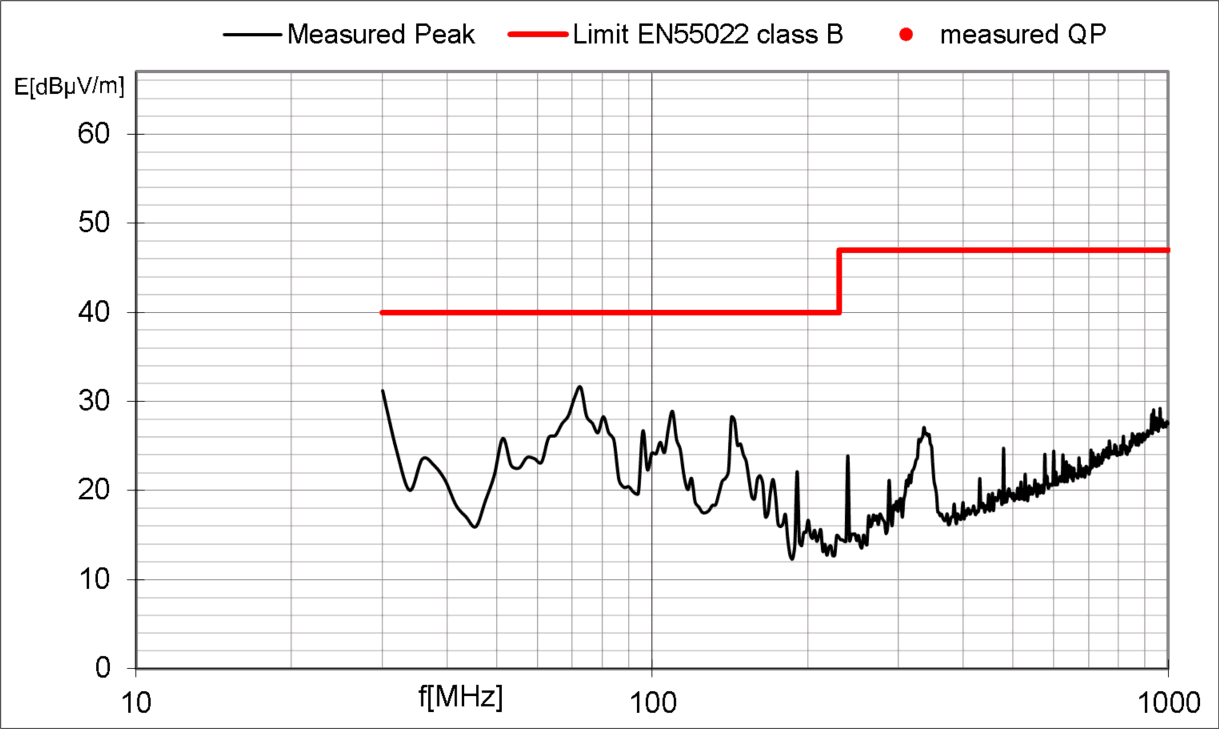
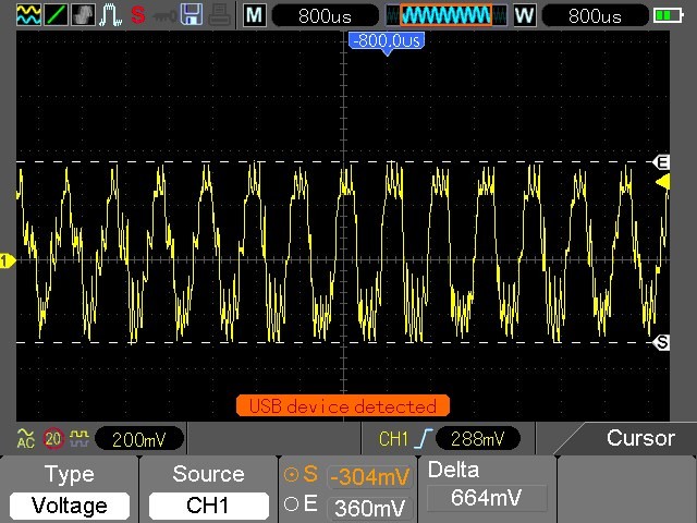
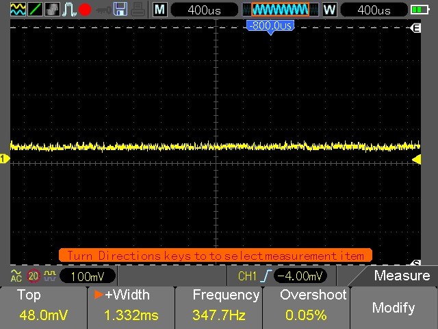
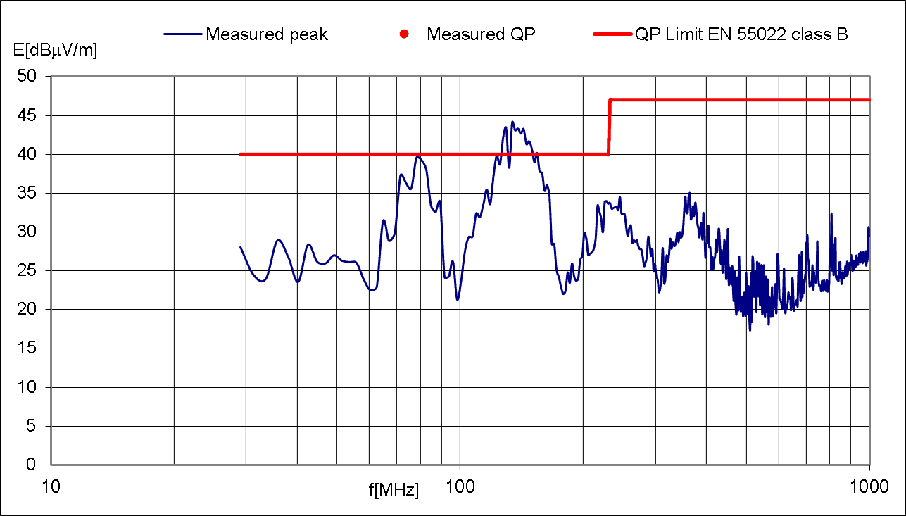
As for the actual UHK measurements, the results are very promising. The measurements of the 2-layer PCB were no more than 4 dB above the limit and no more than 7 dB above the limit with the 4-layer PCB. This is very promising compared to the first round of measurements for which even 16 and 18 dB above-the-limit values were measured.
Endre has a concrete plan regarding the redesign of the PCBs. He’d like to add a common mode choke and ferrite beads at strategic places, and István is ready to redesign the boards accordingly.
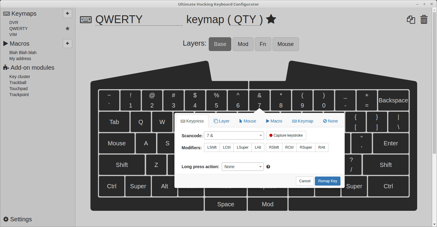
In addition to the changes mentioned above, I plan to implement a number of firmware test features so that we’ll be able to narrow down the cause of various spikes. I think of features like disabling I2C / USB / backlighting and adjusting the clock speed of the MCU with dedicated keys on the keyboard.
I think that with all the above test procedures, test modes, and redesigns in place, we shall defeat the EMC issues with the next prototype, which should be ready in a month.
Due to the EMC hurdles, we must delay delivery by a month. This is frustrating but very much necessary to make the UHK happen. We’re working as hard as we can to hit it soon.
In our true style, we’ll be keeping you up-to-date in our weekly social media updates and monthly newsletters. Thank you for tuning in, and talk to you on 2017-04-13.